Windshield moisture detector

US20050115308A1Inactive Publication Date: 2005-06-02PITTSBURGH GLASS WORKS

Image

  • Windshield moisture detector
  • Windshield moisture detector
  • Windshield moisture detector

Examples


Embodiment Construction

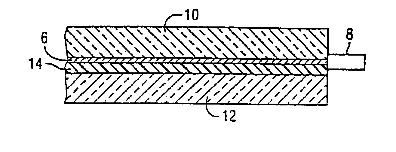
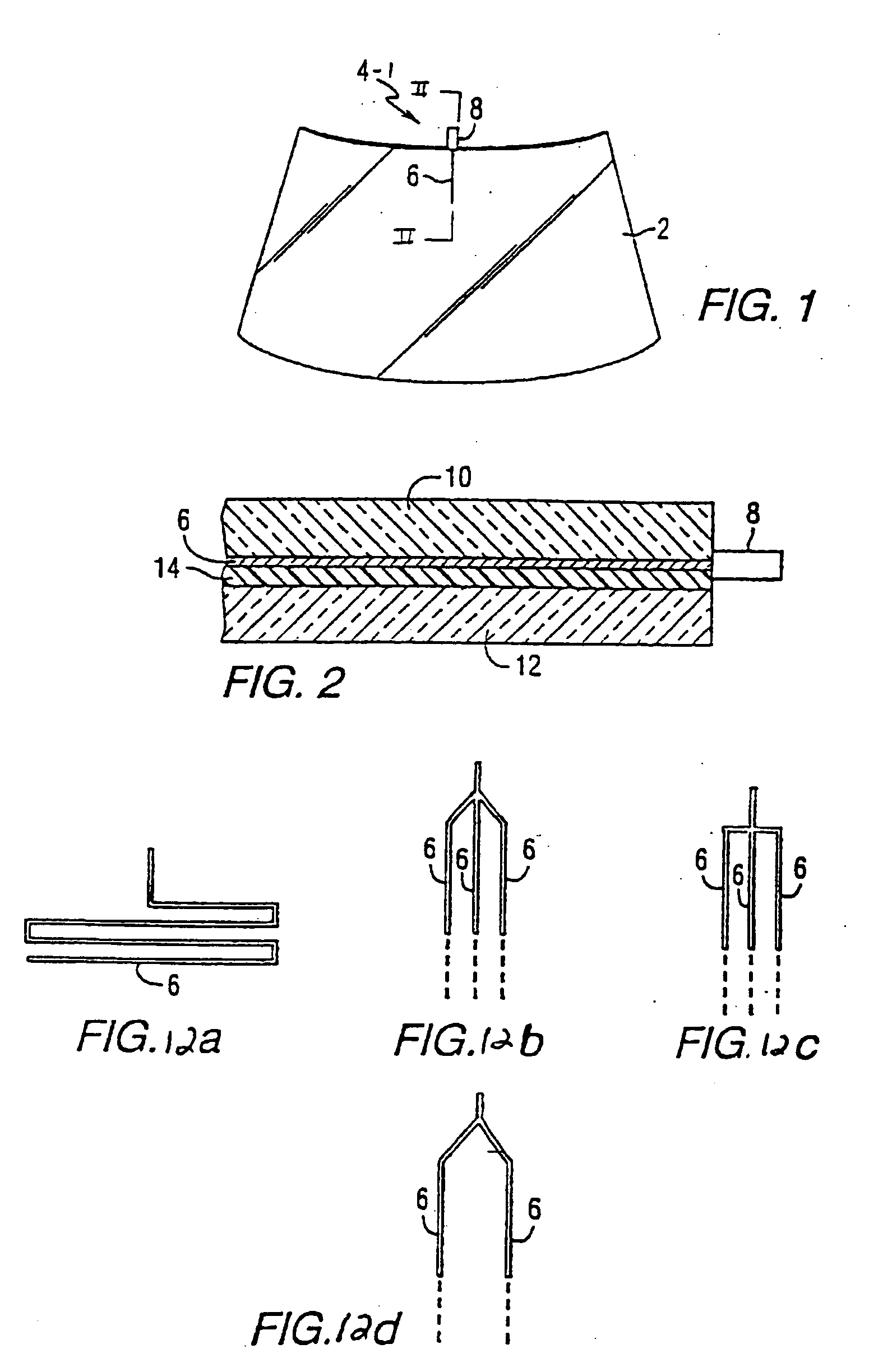
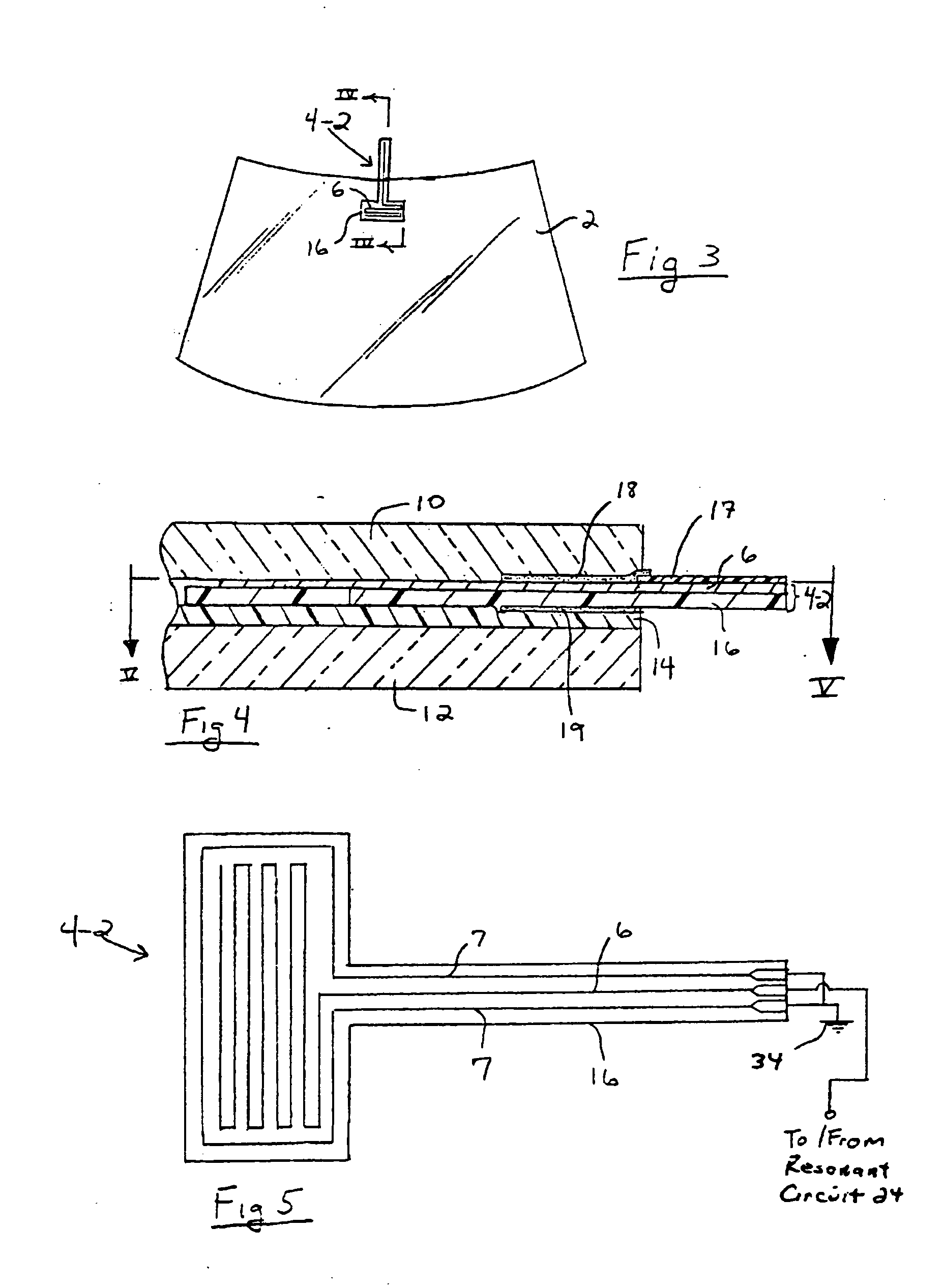
[0050] The present invention will be described with reference to the accompanying figures where like reference numbers correspond to like elements.

[0051] As used herein, spatial or directional terms, such as “inner”, “outer”, “left”, “right”, “up”, “down”, “horizontal”, “vertical”, and the like, relate to the invention as it is shown in the drawing figures. However, it is to be understood that the invention can assume various alternative orientations and, accordingly, such terms are not to be considered as limiting. Further, all numbers expressing dimensions, physical characteristics, and so forth, used in the specification and claims are to be understood as being modified in all instances by the term “about”. Accordingly, unless indicated to the contrary, the numerical values set forth in the following specification and claims can vary depending upon the desired properties sought to be obtained by the present invention. At the very least, and not as an attempt to limit the applica...


PUM

PropertyMeasurementUnit
Temperatureaaaaaaaaaa
Electrical resistanceaaaaaaaaaa
Flexibilityaaaaaaaaaa

Abstract

A moisture detector can include a first elongated conductor disposed on a substrate. The first conductor can define a zigzag path between the opposite ends thereof. A second conductor can also be disposed on the substrate at least partially surrounding the first conductor. The second conductor can define between opposite ends thereof a zigzag path having a portion thereof that is positioned in substantially spaced parallel relation with the zigzag path of the first conductor along the sides thereof. A power conductor disposed on the substrate can be electrically connected to the first conductor intermediate the ends thereof via a gap defined between the ends of the second conductor. Ground conductors disposed on the substrate can be electrically connected to the ends of the second conductor. A temperature sensor can be utilized to correct the response of the moisture detector for temperature.

Description

CROSS REFERENCE TO RELATED APPLICATION [0001] This application is a continuation-in-part of U.S. patent application Ser. No. 10 / 308,670, filed Aug. 28, 2003, which is incorporated herein by reference.BACKGROUND OF THE INVENTION [0002] 1. Field of the Invention [0003] The present invention relates to moisture detection and, more particularly, to moisture detection on a vehicle windshield. [0004] 2. Description of the Prior Art [0005] Heretofore, the detection of moisture on a windshield of a vehicle was accomplished in four basic manners: capacitive sensor systems, resistive sensor systems, ultrasonic sensor systems and optical sensor systems. [0006] A capacitive sensor system includes a capacitor formed on the windshield. In response to moisture on the windshield, the capacitance of the capacitor changes. A sensing circuit is connected to detect the changing capacitance and to control the operation of a windshield wiper as a function of the changing capacitance. Examples of capaciti...

Claims


Application Information

Patent Timeline
02 Jun 2005
Publication
US20050115308A1
IPC
B60S1/08; G01F23/26; G01N25/56; G01N27/02
CPC
B32B17/10036; B32B17/10174; B32B17/10376; B32B17/10761; G01N27/223; B60S1/0829; B60S1/0877; B60S1/50
Inventors
KORAM, KWAKU K.; HAWK, ALLEN R.