Method of camouflaging defective print elements in a printer

Active Publication Date: 2005-06-02
OCE TECH
View PDF3 Cites 19 Cited by
  • Summary
  • Abstract
  • Description
  • Claims
  • Application Information

AI Technical Summary

Benefits of technology

[0010] It is an object of the invention to provide a method with which image defects that

Problems solved by technology

When a nozzle of the printhead becomes defective, e.g. becomes clogged, the corresponding pixel line fails to print in the printed image, so that image information is lost and th

Method used


Image

  • Method of camouflaging defective print elements in a printer
  • Method of camouflaging defective print elements in a printer
  • Method of camouflaging defective print elements in a printer

Examples


Embodiment Construction

[0036] Advantages of the present invention will become more apparent from the detailed description given hereinafter. However, it should be understood that the detailed description and specific examples, while indicating preferred embodiments of the invention, are given by way of illustration only, since various changes and modifications within the spirit and scope of the invention will become apparent to those skilled in the art from this detailed description.

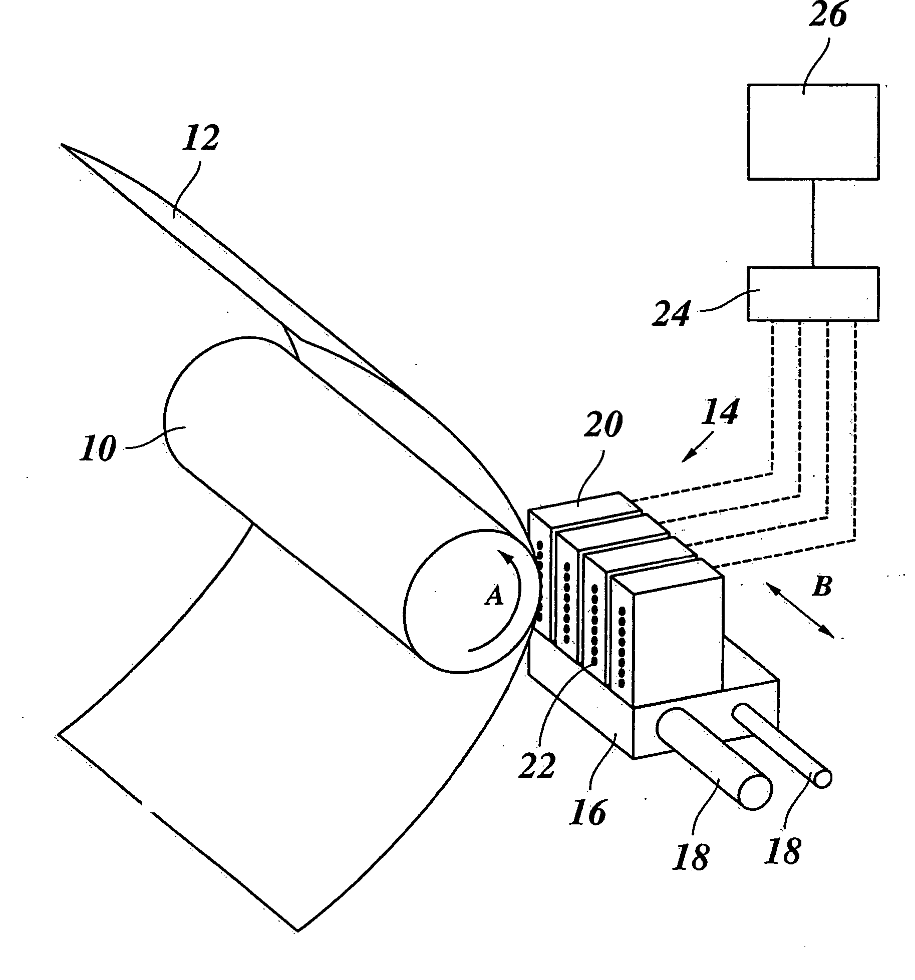
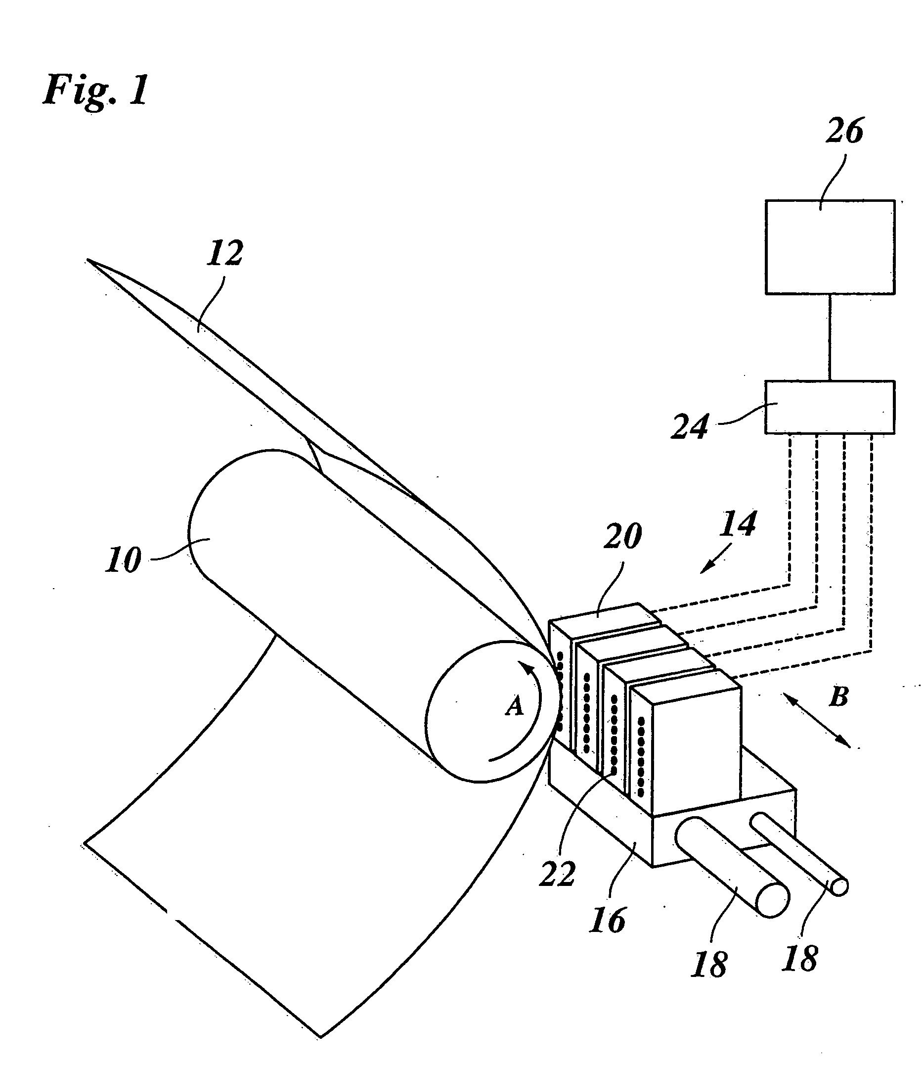
[0037]FIG. 1 shows an ink jet printer that includes a platen 10 which serves to transport a recording paper 12 in a subscanning direction (arrow A) past a printhead unit 14. The printhead unit 14 is mounted on a carriage 16 that is guided on guide rails 18 and is movable back and forth in a main scanning direction (arrow B) relative to the recording paper 12. In the example shown, the printhead unit 14 includes four printheads 20, one for each of the basic colors cyan, magenta, yellow and black. Each printhead has a linear ar...


PUM


Abstract

A method of camouflaging defective print elements in a printer having a printhead with print elements, and each pixel of the image is assigned to a print element, and image information of a pixel that is assigned to a defective print element shifts to a nearby pixel position capable of printing with a non-defective print element. Shifting the image information includes the steps of a) encoding the image information to be printed as a multi-level pixel matrix in which one of a predetermined set of pixel values (“0”, “1”, “2”) is assigned to each pixel and at least one of the pixel values is a conditional pixel value (“1”) encoding a print instruction that depends upon whether or not a neighbouring pixel corresponds to a defective print element, b) determining defective print elements of the printer, and c) executing the print instruction.

Description

[0001] This application claims benefit under 35 U.S.C. §119 of European patent application no. 03078754.3, filed Nov. 27, 2003, the entire contents of which is hereby incorporated by reference. BACKGROUND OF THE INVENTION [0002] 1. Field of the Invention [0003] The invention relates to a method of camouflaging defective print elements in a printer having a printhead with multiple print elements, where each pixel of the image is assigned to a print element with which it is to be printed, and image information of a pixel assigned to a defective print element is shifted to a nearby pixel position where it can be printed by a non-defective print element. The invention also relates to a printer and to a computer program implementing this method. [0004] 2. Description of the Related Art [0005] In an ink jet printer, the printhead contains multiple nozzles as print elements. Typically, the nozzles are arranged in a line that extends in parallel with a direction (subscanning direction) in w...

Claims


Application Information

Patent Timeline
IPC IPC(8): B41J2/01B41J2/165B41J2/21B41J2/255B41J2/485B41J2/51G06K15/10H04N1/23H04N1/40
CPCB41J2/2139G06K2215/0085G06K15/107
Inventor FAKEN, HENRYVESTJENS, JOHANNES C.G.
Owner OCE TECH
Why Eureka
Try Eureka