Selecting a magnetic memory cell write current

Active Publication Date: 2005-06-02
SAMSUNG ELECTRONICS CO LTD
View PDF3 Cites 1 Cited by
  • Summary
  • Abstract
  • Description
  • Claims
  • Application Information

AI Technical Summary

Benefits of technology

[0010] The invention includes an apparatus and method for selecting a magnetic memory cell write current. The apparatus and method selects a magnitude

Problems solved by technology

Clearly, half-select errors degra

Method used


Image

  • Selecting a magnetic memory cell write current
  • Selecting a magnetic memory cell write current
  • Selecting a magnetic memory cell write current

Examples


Embodiment Construction

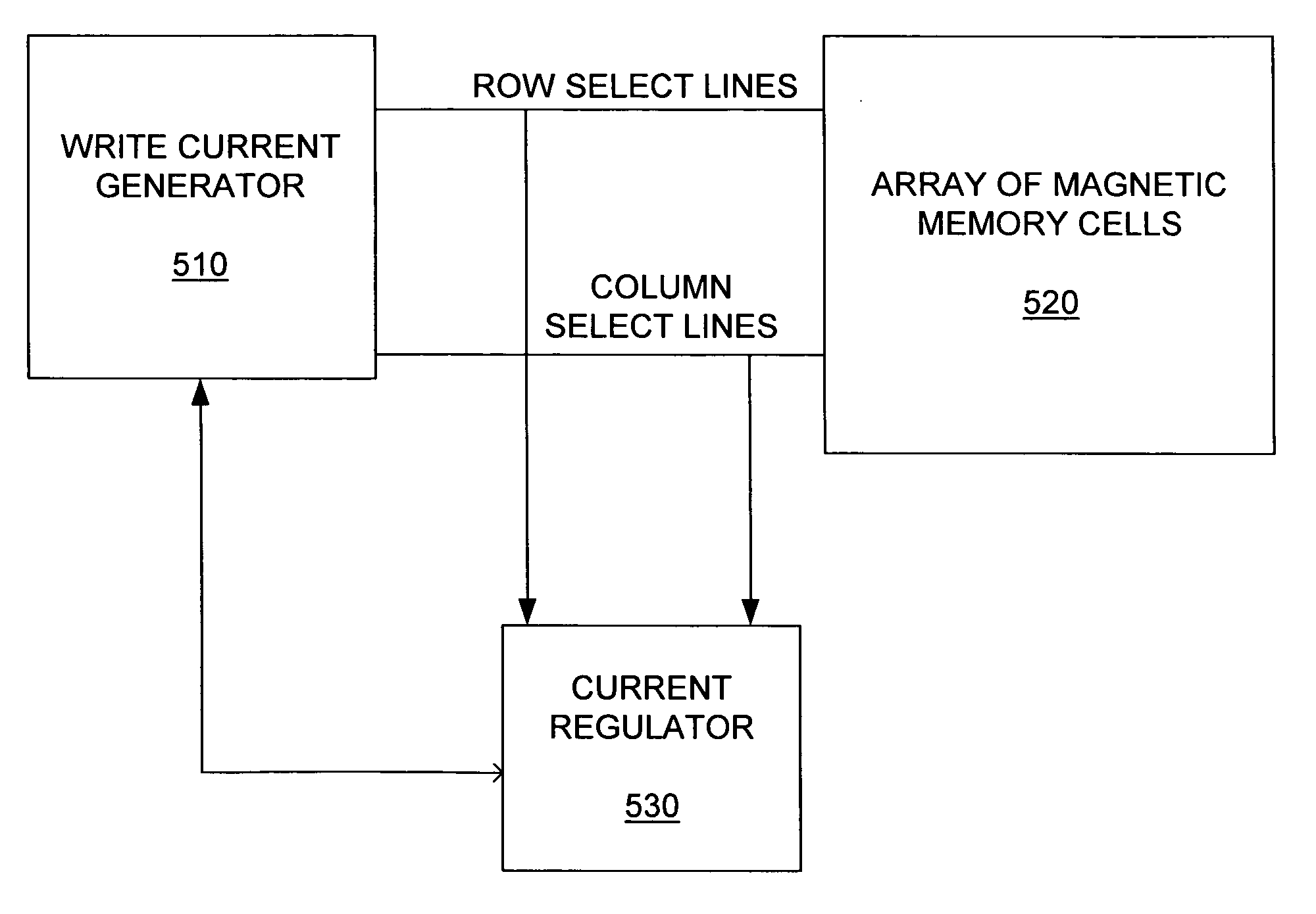
[0025] The invention includes an apparatus and method of writing to magnetic memory cells. The apparatus and method minimizes half-select errors while still providing write operations to the MRAM memory cells that are consistent and reliable.

[0026]FIG. 3 is a plot showing a relationship between magnetic memory write current and possible magnetic memory write errors. FIG. 3 shows that when the write current is below a first threshold current (I1), then memory cell write errors occur. If the write current is below the first threshold (I1), the magnetic field created by the write current is too small to consistently write to the memory cells.

[0027]FIG. 3 shows that if the write current to a magnetic memory cell within an array of magnetic memory cells is greater than a second threshold current (I2), then magnetic memory cells within the array are likely to suffer from half select errors. Half-select errors occur when a memory cell associated with a selected bit line and a non-selecte...


PUM


Abstract

The invention includes an apparatus and method for selecting a desirable magnitude of a magnetic memory cell write current. The method includes determining a minimal magnitude of write current for writing to the magnetic memory cell, determining a maximal magnitude of write current for writing to the magnetic memory cell, and calculating the selected magnitude of magnetic memory cell write current based on the minimal magnitude of write current and the maximal magnitude of write current.

Description

RELATED APPLICATIONS [0001] This patent application is a continuation-in-part (CIP) of patent application Ser. No. 10,725,803, filed Dec. 2, 2003.FIELD OF THE INVENTION [0002] The invention relates generally to electronic memory. More particularly, the invention relates to an apparatus and method for selecting a magnetic memory cell write current. BACKGROUND OF THE INVENTION [0003] Non-volatile memory is memory that retains its content (data) even when power connected to the memory is turned off. Magnetic random access memory (MRAM) is a type of non-volatile memory. A logical state, or bit, is stored in MRAM by setting magnetic field orientations of MRAM cells within the MRAM. The magnetic field orientations remain even when power to the MRAM cells is turned off. [0004]FIG. 1 shows an MRAM cell 100. The MRAM memory cell 100 includes a soft magnetic region 120, a dielectric region 130 and a hard magnetic region 110. The orientation of magnetization within the soft magnetic region 120...

Claims


Application Information

Patent Timeline
IPC IPC(8): G11C11/15G11C7/04G11C7/22G11C11/00G11C11/02G11C11/16G11C29/00H01L21/8246H01L27/105
CPCG11C11/16
Inventor PERNER, FREDERICK A.
Owner SAMSUNG ELECTRONICS CO LTD
Why Eureka
Try Eureka