Method and device for regulating fluid pump pressures

Inactive Publication Date: 2005-06-02
DEKA PROD LLP
View PDF79 Cites 22 Cited by
  • Summary
  • Abstract
  • Description
  • Claims
  • Application Information

AI Technical Summary

Benefits of technology

[0005] A method is provided for regulating fluid pump pressures based on the relative elevation between a fluid flow control device and a distal end of a fluid line by providing at least one liquid volume in valved communication with the distal end. The pressure measurement of the li

Problems solved by technology

One problem with respect to fluid flow control d

Method used


Image

  • Method and device for regulating fluid pump pressures
  • Method and device for regulating fluid pump pressures
  • Method and device for regulating fluid pump pressures

Examples


Embodiment Construction

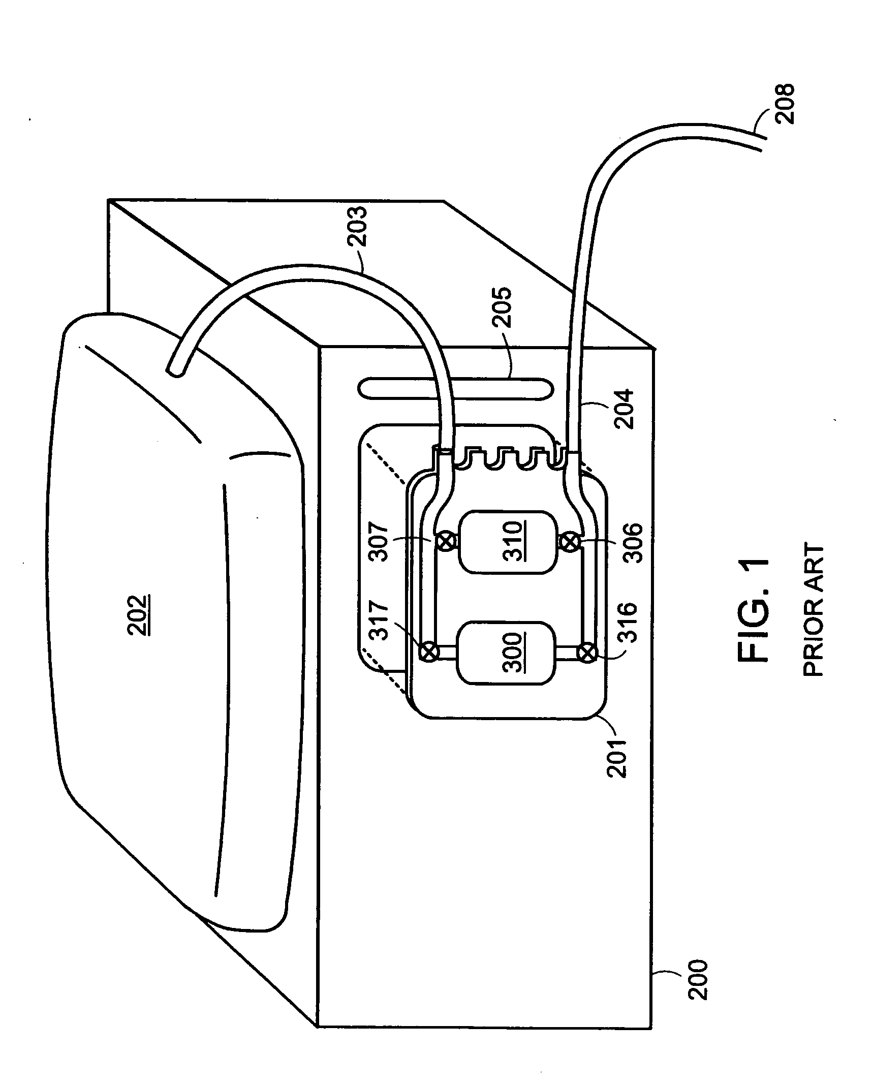
[0018]FIG. 1 shows a prior art fluid flow control device 200. A disposable cassette 201 is securely mounted onto the fluid flow control device 200. Fluid communication with the cassette 201 is maintained from a heated solution bag 202 via a solution inlet line 203 and is also maintained to a distal end 208 of an outlet line 204. The fluid flow control device 200 has an occluder bar 205 that when activated by the fluid flow control device 200, occludes both the inlet line 203 and the outlet line 204. The fluid flow control device 200 is shown to have two pumps 300 and 310, each pump having inlet and outlet valves 306, 307, 316, and 317.

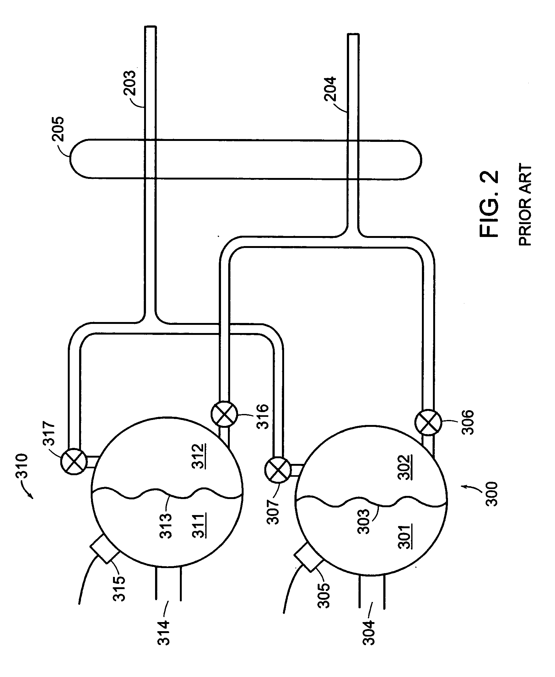
[0019]FIG. 2 illustrates a membrane-based fluid control flow system utilized in fluid flow control device 200 of FIG. 1 and having a first pump 300 and a second pump 310. Flexible membrane 303 is shown as dividing first pump 300 into a first control volume 301 and a first liquid volume 302. The first control volume 301 may be pressurized through a fir...


PUM


Abstract

A method is provided for regulating fluid pump pressures by detecting an elevation differential between a fluid flow control device and the distal end of a fluid line in communication with the fluid flow control device. A fluid flow control device, for instance a peritoneal dialysis device, is at a first height, a distal end of a fluid line is at a second height, and a valved outlet, when open, affords communication between the fluid flow control device and the distal end of the fluid line. The elevation differential is correlatable with a pressure measurable during a calibration procedure provided as a part of the methodology.

Description

[0001] The present application is a divisional of U.S. application Ser. No. 09 / 612,005 (now U.S. Pat. No. 6,503,062) which is incorporated herein, in its entirety, by reference.TECHNICAL FIELD [0002] The present invention relates to fluid flow control devices and, more specifically, to regulating pump pressures. In particular, the invention provides a method and apparatus for increasing the fluid flow rate in a fluid flow control device while maintaining desired pressure levels. The present invention also relates to systems that can determine the relative elevation of a pump with respect to a distal end of a line in communication with the pump. BACKGROUND ART [0003] A function of fluid flow control systems is to regulate the rate of distribution of transport fluid through a line. Some examples of fluid control devices are peritoneal dialysis machines and intravenous fluid delivery systems. Fluid flow control systems may include a permanent housing which does not come into direct con...

Claims


Application Information

Patent Timeline
IPC IPC(8): F04B49/00A61M1/14A61M1/28A61M5/00A61M5/168F04B9/103F04B43/04F04B43/06G05D16/20
CPCA61M5/16809A61M2205/3331F04B43/043A61M1/282G05D16/2073G05D7/0635F04B43/06Y10T137/0318A61M1/155A61M1/1565A61M1/159A61M1/152
Inventor GRAY, LARRYBRYANT, ROBERT
Owner DEKA PROD LLP
Why Eureka
Try Eureka