
Haptic graphical user interface for adjusting mapped texture

a user interface and graphical technology, applied in the field of graphical user interfaces, can solve the problems of unsatisfactory texture mapping accuracy, and inability to map texture onto three-dimensional models

Active Publication Date: 2005-06-16
3D SYST INC
View PDF99 Cites 45 Cited by
  • Summary
  • Abstract
  • Description
  • Claims
  • Application Information

AI Technical Summary

Benefits of technology

[0011] The invention also provides a haptic / graphical user interface element for adjusting mapped texture. The element allows a user to interactively and intuitively adjust texture mapped within an arbitrarily-shaped, user-defined region on the surface of a 3D virtual object.
[0055] The code may further include a selection module adapted to select one of the hotspots based on a two-dimensional correspondence of the active location and the cursor / tool. This module allows “view-apparent” selection of a hotspot, such that depth is effectively collapsed for purposes of selection. This makes it easier for a user to find and select a given hotspot. As part of the “view-apparent” functionality, the code may further include a repositioning module adapted to move the cursor / tool to a 3D position corresponding to one of the hotspots of the graphical user interface element.

Problems solved by technology

Prior texture mapping techniques often introduce an unacceptable amount of distortion, particularly where the three-dimensional model has a complex geometry.
However, spherical projection introduces unacceptable distortion of the mapped texture if the object is non-spherical or has non-spherical portions.
Similarly, planar projection and cylindrical projection methods do not work well for mapping texture onto three-dimensional models having non-planar or non-cylindrical portions.
Many realistic objects—for example, shoes—do not match well to any of the available projection methods.
As a result, the application of a two-dimensional texture to the surface of such objects results in significant, unavoidable distortion of the two-dimensional texture.
Moreover, prior texture mapping methods are not sufficiently robust.
Furthermore, prior texture mapping methods are difficult for a user to apply because they require the user to provide input in a non-intuitive, multi-step manner.
Consequently, the process of positioning, scaling, and rotating the texture into its desired configuration is often difficult and time-consuming.

Method used


Image

  • Haptic graphical user interface for adjusting mapped texture
  • Haptic graphical user interface for adjusting mapped texture
  • Haptic graphical user interface for adjusting mapped texture

Examples


Embodiment Construction

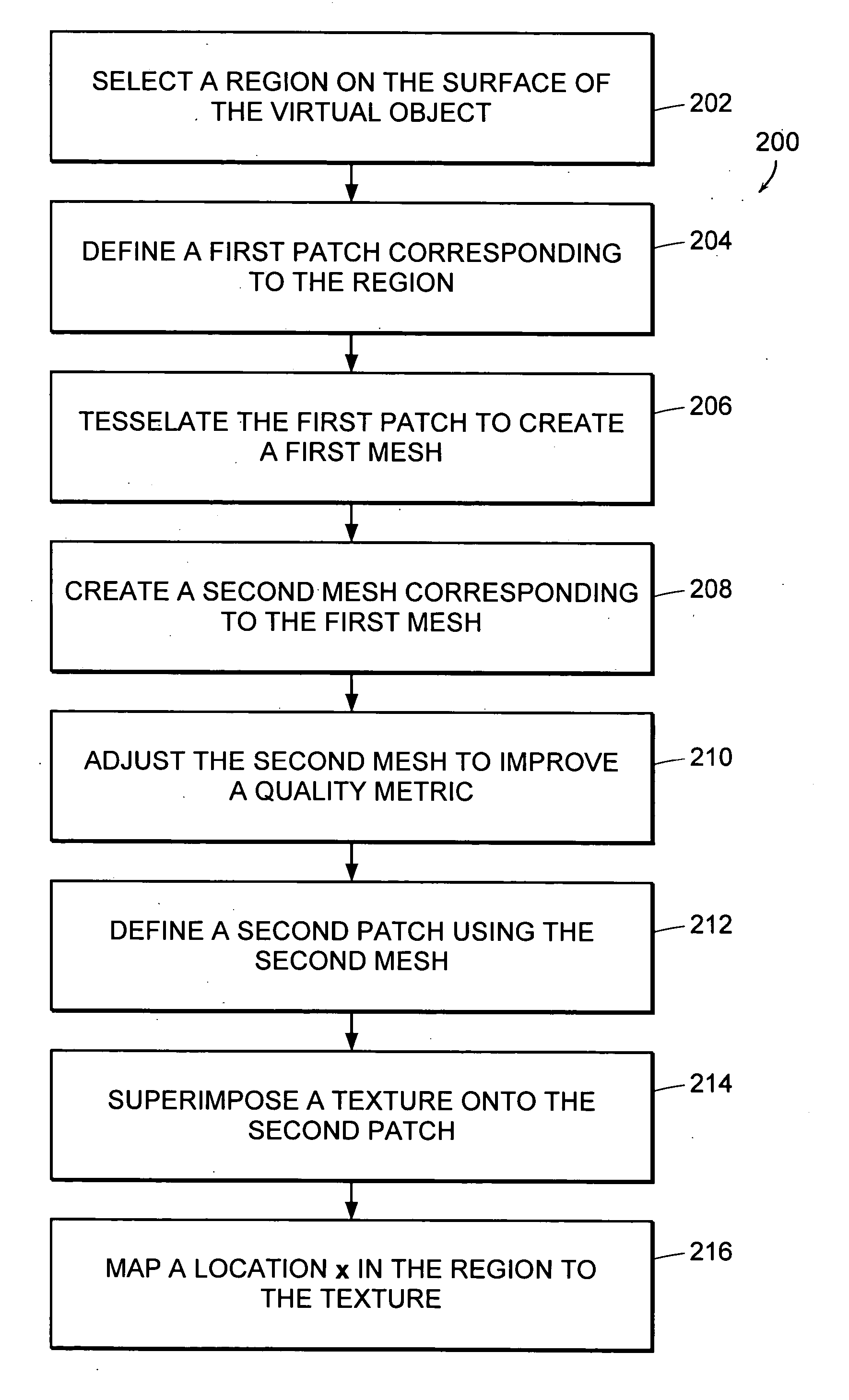
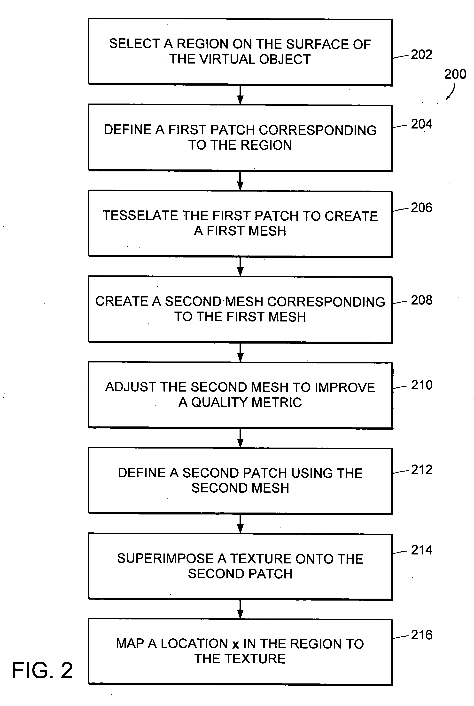
[0098] The invention provides improved methods for mapping a point on the surface of a three-dimensional (3D) virtual object onto a corresponding point on a two-dimensional (2D) texture. By using these mapping methods, it is possible to wrap a 2D texture onto the surface of a 3D virtual object within an arbitrarily-shaped, user-defined region in a way that minimizes the distortion of the wrapped texture.

[0099] Texture mapping is a process by which points on the surface of a virtual object are related to points of a texture. For example, a point on the surface of a 3D virtual object can be mapped to a point on a 2D surface; or, equivalently, a point on the 2D surface can be mapped to a point on the surface of the 3D virtual object. The 3D virtual object is generally represented in object space, for example, as a system of elements and / or points in a Cartesian (x,y,z) coordinate system.

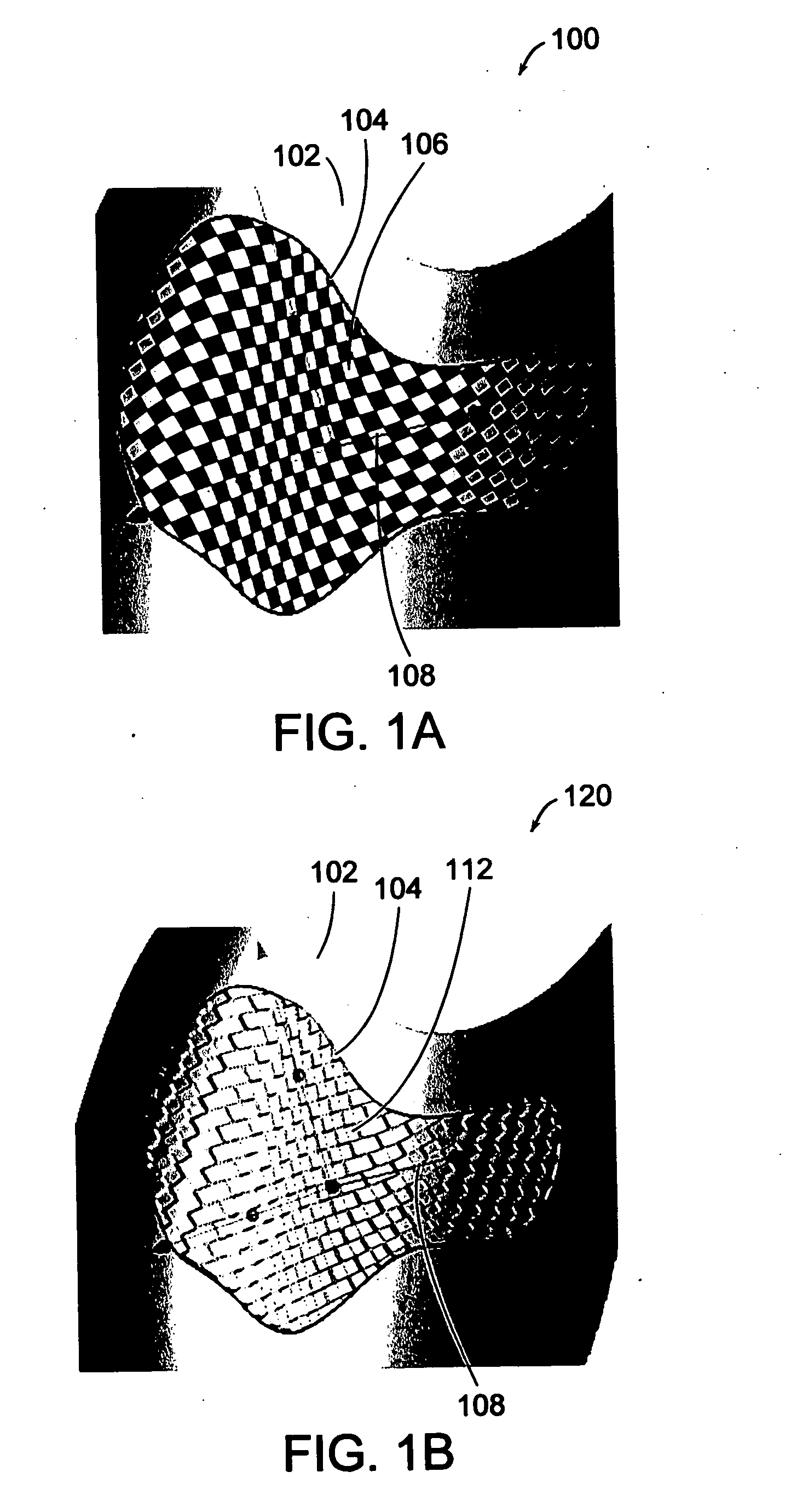
[0100]FIG. 1A is a screenshot 100 of a three-dimensional object 102 where locations within a user-...


PUM


Abstract

The invention provides techniques for wrapping a two-dimensional texture conformally onto a surface of a three dimensional virtual object within an arbitrarily-shaped, user-defined region. The techniques provide minimum distortion and allow interactive manipulation of the mapped texture. The techniques feature an energy minimization scheme in which distances between points on the surface of the three-dimensional virtual object serve as set lengths for springs connecting points of a planar mesh. The planar mesh is adjusted to minimize spring energy, and then used to define a patch upon which a two-dimensional texture is superimposed. Points on the surface of the virtual object are then mapped to corresponding points of the texture. The invention also features a haptic / graphical user interface element that allows a user to interactively and intuitively adjust texture mapped within the arbitrary, user-defined region.

Description

RELATED APPLICATIONS [0001] This application is related to the commonly-owned U.S. patent application entitled, “Apparatus and Methods for Wrapping Texture Onto the Surface of a Virtual Object,” by Berger et al., filed under Attorney Docket No. SNS-013 on even date herewith, the text of which is hereby incorporated by reference in its entirety.FIELD OF THE INVENTION [0002] This invention relates generally to graphical user interfaces. More particularly, in certain embodiments, the invention relates to a haptic / graphical user interface for adjusting texture mapped onto the surface of a virtual object. BACKGROUND OF THE INVENTION [0003] Certain computer graphics applications allow a user to apply a two-dimensional texture onto the surface of a three-dimensional model. For example, a graphics package may allow a user to cover the surface of a sphere or a cylinder with a two-dimensional checkerboard pattern. [0004] A two-dimensional texture must generally be distorted to some extent in ...

Claims


Application Information

Patent Timeline
Patent Type & Authority Applications(United States)
IPC IPC(8): G09G5/00
CPCG06T15/04G06F3/1446G09G5/00Y10S715/964
Inventor BERGER, TORSTEN
Owner 3D SYST INC
Learn More