

Apparatus and method for fusion reactor
- Summary
- Abstract
- Description
- Claims
- Application Information
AI Technical Summary
Problems solved by technology
Method used
Image

Examples
Embodiment Construction
[0024] Throughout the following description, specific details are set forth in order to provide a more thorough understanding of the invention. However, the invention may be practiced without these particulars. In other instances, well known elements have not been shown or described in detail to avoid unnecessarily obscuring the invention. Accordingly, the specification and drawings are to be regarded in an illustrative, rather than a restrictive, sense.
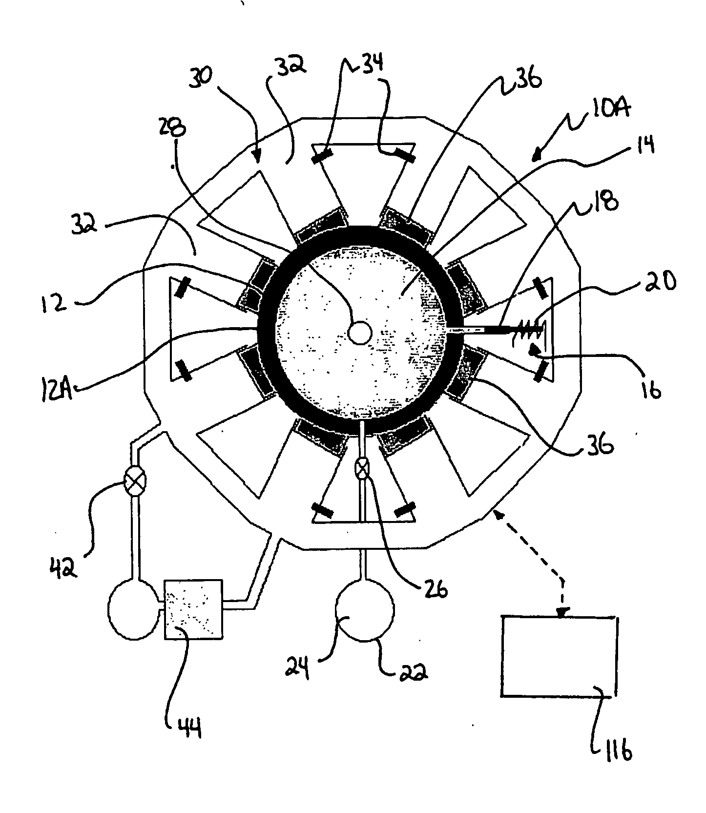
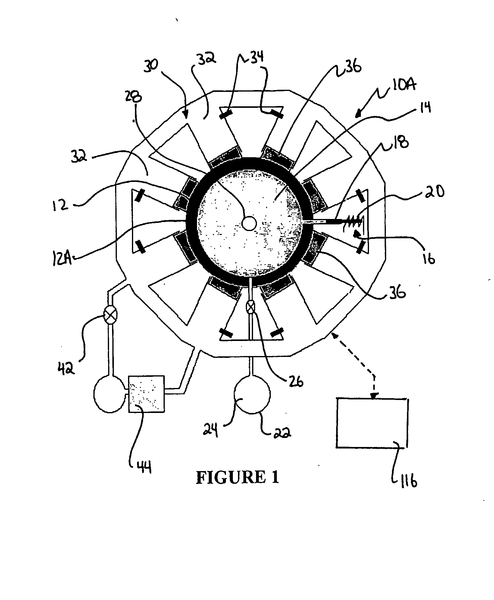
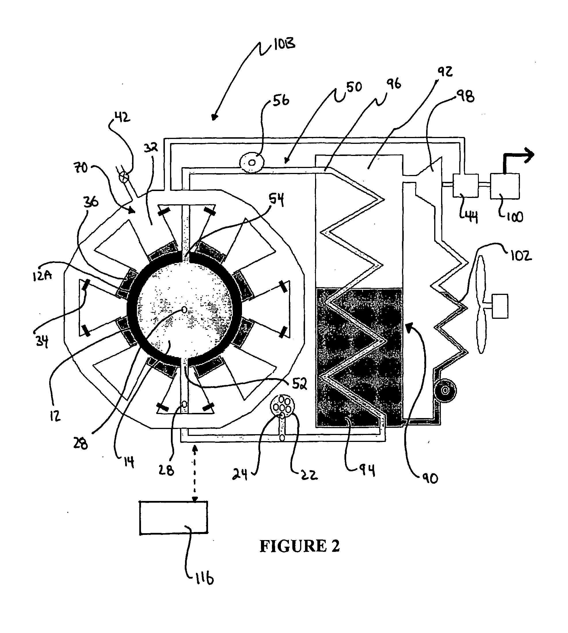
[0025] This invention provides methods and apparatus which implement a “bubble compression” fusion reactor. The invention involves creating a spherically symmetric positive acoustic pulse in a liquid which contains a spherical bubble of fusionable material. The acoustic pulse compresses and collapses the bubble to correspondingly increase the pressure and temperature of the fusionable material contained therein. At the surface of the bubble, the peak pressure of the acoustic pulse is significantly greater than that achievable using ...
PUM
 Abstract
Description
Claims
Application Information