Compact fusion reactor

A reactor, compact technology, applied in thermonuclear fusion reactor, fusion reactor, nuclear reactor, etc.

Inactive Publication Date: 2013-05-01
TOKAMAK ENERGY
View PDF2 Cites 18 Cited by
  • Summary
  • Abstract
  • Description
  • Claims
  • Application Information

AI Technical Summary

Problems solved by technology

Although the magnetic field and current requirements have been greatly reduced compared to power plant requirements, they are still considerable and, in addition t

Method used


Image

  • Compact fusion reactor
  • Compact fusion reactor
  • Compact fusion reactor

Examples


Embodiment Construction

[0032] For a 14 MeV neutron source, several options have been considered based on tokamaks with a fusion output of at least 1 MW, including:

[0033] a. A tokamak with a superconducting magnet and an aspect ratio A=3-4 (A=R / a-the ratio of the major axis radius R of the ring to the minor axis radius a);

[0034] b. Low aspect ratio tokamak with copper or superconducting magnets and aspect ratio A=2;

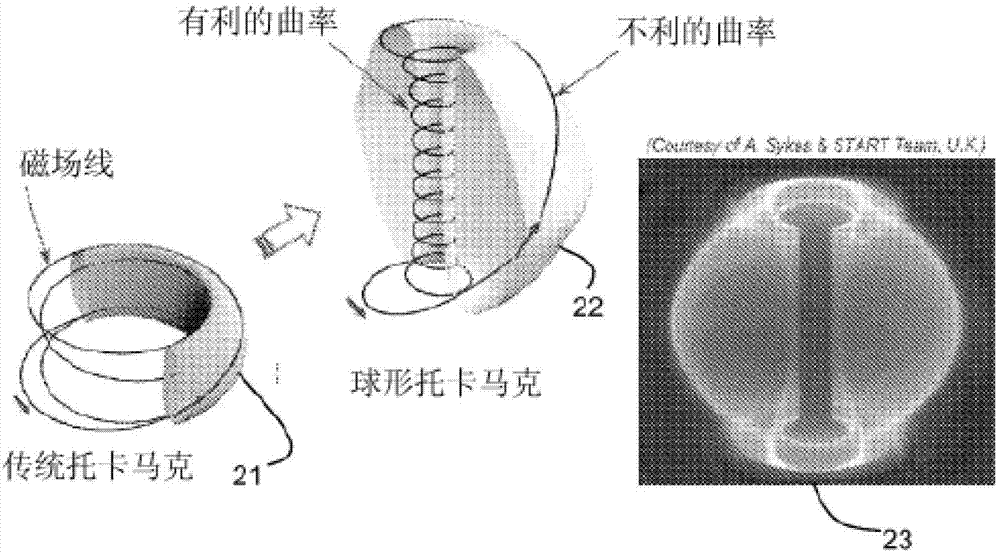
[0035] c. Compact spherical tokamak with copper magnets and aspect ratio A = 1.5-1.8;

[0036] d. A spherical tokamak with copper or superconducting magnets and an aspect ratio of 1.5-1.8.

[0037] From a technical point of view, all options appear to be achievable and deliver the required power levels. Option (a) has the lowest plasma and neutron loading, but its cost will exceed 1 billion euros.

[0038] Option (b) has certain advantages in terms of manufacturing, and the cost of the tokamak can be reduced compared to option (a). However, option (b) has considerable power re...


PUM

PropertyMeasurementUnit
Radiusaaaaaaaaaa
Radiusaaaaaaaaaa

Abstract

A compact nuclear fusion reactor for use as a neutron source is described. The reactor comprises a toroidal plasma chamber (34) and a plasma confinement system (31) arranged to generate a magnetic field for confining a plasma in the plasma chamber (34). The plasma confinement system (31) is configured so that a major radius of the confined plasma is 0.75 m or less. The reactor is configure to operate with a plasma current of 2 MA or less. The magnetic field includes a toroidal component of 5 T or less. Despite these low values, the reactor can generate a neutron output of 1 MW or more.

Description

technical field [0001] The present application relates to a compact nuclear fusion reactor. In particular, but not exclusively, the invention relates to spherical tokamak reactors suitable for use as neutron sources. Background technique [0002] After the start of the construction of the ITER (International Thermonuclear Experimental Reactor) project, the world's nuclear fusion research has entered a new era. However, a successful route to commercial fusion reactors requires long pulses, high efficiency and stable operation that make electricity generation economical. These three conditions are particularly difficult to achieve simultaneously, and the scheme will require years of continuous experimental research on ITER and other fusion facilities, as well as theoretical and technical research. [0003] A more immediate application of nuclear fusion is the use of nuclear fusion devices as neutron sources, which can be used in a variety of applications (including the produ...

Claims


Application Information

Patent Timeline
IPC IPC(8): G21B1/05H05H1/12H05H3/06
CPCY02E30/126G21B1/05Y02E30/128Y02E30/122G21B1/057H05H3/06Y02E30/10H05H1/12
Inventor 阿兰·赛克斯米哈尔·格瑞亚耐维奇
Owner TOKAMAK ENERGY
Why Eureka
Try Eureka