Method for connecting materials difficult to connect through ultrafast lasers

A technology for connecting materials and ultra-fast lasers, applied in laser welding equipment, welding equipment, metal processing equipment, etc., can solve the problems of difficult connection and low connection strength, and achieve the elimination of heat affected zone, flexible connection methods, and rich forms. Effect

Active Publication Date: 2015-03-25
TSINGHUA UNIV
View PDF4 Cites 18 Cited by
  • Summary
  • Abstract
  • Description
  • Claims
  • Application Information

AI Technical Summary

Problems solved by technology

However, for dissimilar materials that have low solid solubility and do not form compounds at room temperature, such as W/Cu, Mo/Cu, ceramics/Al, it is

Method used


Image

  • Method for connecting materials difficult to connect through ultrafast lasers
  • Method for connecting materials difficult to connect through ultrafast lasers
  • Method for connecting materials difficult to connect through ultrafast lasers

Examples


Embodiment 1

[0043] Example 1, fs laser preparation of micro-protrusion arrays on W surface to enhance W / Cu connection strength

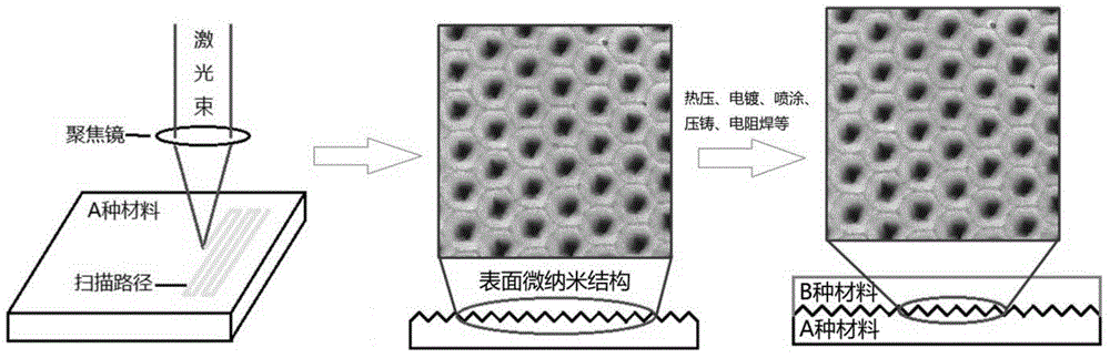
[0044] In this example, the fs laser is used to prepare micro-protrusion arrays on the W surface to enhance the connection strength of the W / Cu thermocompression connector. The flow chart is as follows figure 1 As shown, the specific steps are as follows:

[0045] (1) First remove the oxide on the end face of the W rod by mechanical processing, and remove the oxide on the end face of the Cu rod by chemical corrosion (etching agent: dilute hydrochloric acid with a volume fraction of 5%), and then use a grinding and polishing machine to clean the W rod. Grinding and polishing with the end face of the Cu rod, then ultrasonically cleaning the W rod and the Cu rod with alcohol, and finally blowing them dry with a high-pressure nitrogen stream. Among them, the size of the W rod is Φ10mm×5mm, and the size of the Cu rod is Φ10mm×30mm.

[0046] (2) Prepare the micro-n...

Embodiment 2

[0057] Example 2, fs laser preparation of micro-pit arrays on W surface to enhance W / Cu connection strength

[0058] In this example, the fs laser is used to prepare a micro-pit array on the W surface to enhance the connection strength of the W / Cu thermocompression connection. The schematic flow diagram is as follows figure 1 As shown, the specific steps are as follows:

[0059] (1) First remove the oxide on the end face of the W rod by mechanical processing, and remove the oxide on the end face of the Cu rod by chemical corrosion (etching agent: dilute hydrochloric acid with a volume fraction of 5%), and then use a grinding and polishing machine to clean the W rod. Grinding and polishing with the end face of the Cu rod, then ultrasonically cleaning the W rod and the Cu rod with alcohol, and finally blowing them dry with a high-pressure nitrogen stream. Among them, the size of the W rod is Φ10mm×5mm, and the size of the Cu rod is Φ10mm×30mm.

[0060] (2) Prepare the micro-n...


PUM

PropertyMeasurementUnit
Pulse widthaaaaaaaaaa
Average poweraaaaaaaaaa
Sizeaaaaaaaaaa

Abstract

The invention discloses a method for connecting materials difficult to connect through ultrafast lasers. The method includes the following steps that firstly, a material A is ablated through ultrashort pulse lasers, removing is achieved through laser ablation, and a nano-micro-meter structure is obtained on the surface of the material A; secondly, impurities on the surface, with the nano-micro-meter structure, of the material A are removed through corrosive liquid; thirdly, in an inert gas or vacuum environment, a material B is deformed and flows to fill the nano-micro-meter structure of the material A, the material A and the material B are combined in a mechanical combination mode, and therefore the material A and the material B are connected, wherein the melting point and the hardness of the material A are higher than the melting point and the hardness of the material B. The method for connecting the materials difficult to connect through the ultrafast lasers is a new method which is flexible, high in efficiency and wide in application range and is used for improving the connecting strength of the materials, and the application of the method includes but is not limited to the development of a nuclear fusion reactor oriented to plasma materials, electric contact materials, heat sink materials, electronic packaging and advanced composite materials.

Description

technical field [0001] The invention relates to a method for realizing connection between difficult-to-connect materials by using an ultrafast laser, and belongs to the field of material connection. Background technique [0002] The surface micro-nano structure is a regular structure with micron, nanometer or micro-nano composite scales prepared on the surface of the material through specific processing methods. Common structural forms include stripes, protrusions (hemispherical, cone-shaped, rod-shaped) and pits, etc. , and composite forms of the above structures. The surface micro-nanostructure has the characteristics of superhydrophobicity, superviscosity, anti-light reflection, selective light absorption, etc., and has broad application prospects in various fields such as industry, military, aviation, aerospace, and medical treatment. Commonly used surface micro-nanostructure preparation methods include CVD method, sol-gel method, template method, self-assembly method, ...

Claims


Application Information

Patent Timeline
IPC IPC(8): B23P15/00B23K26/362
CPCB23P15/00
Inventor 钟敏霖江大发张红军
Owner TSINGHUA UNIV
Why Eureka
Try Eureka