H-bridge with sensing circuit

a sensing circuit and hbridge technology, applied in the field of defibrillation/cardioversion systems, can solve the problems of no practical use, no use, and system is far more complicated to use, and achieve the effect of avoiding interference with the heart signal of the patien

Inactive Publication Date: 2005-06-16
CAMERON HEALTH
View PDF46 Cites 0 Cited by
  • Summary
  • Abstract
  • Description
  • Claims
  • Application Information

AI Technical Summary

Benefits of technology

[0019] An electrical circuit for a cardioverter-defibrillation system includes an energy storage device such as a capacitor, an output circuit for controlling delivery of defibrillation pulses from the energy storage device to a patient, and a sensing circuit coupled across the patient to sense the patient's heart signal. The output circuit may be in the form of an H-bridge switching circuit wherein a pair of switches of the output circuit is simultaneously turned on to discharge residual voltage across the patient that remains after delivery of defibrillation pulses. Thus, interference with sensing of the patient's heart signal is avoided.

Problems solved by technology

This system is far more complicated to use than current ICD systems using transvenous lead systems together with an active can electrode and therefore it has no practical use.
It has in fact never been used because of the surgical difficulty of applying such a device (3 incisions), the impractical abdominal location of the generator and the electrically poor sensing and defibrillation aspects of such a system.
ICDs are very effective at treating V-Fib, but are therapies that still require significant surgery.
In addition, chronic transvenous lead systems, their reimplantation and removals, can damage major cardiovascular venous systems and the tricuspid valve, as well as result in life threatening perforations of the great vessels and heart.
Consequently, use of transvenous lead systems, despite their many advantages, are not without their chronic patient management limitations in those with life expectancies of >5 years.
The problem of lead complications is even greater in children where body growth can substantially alter transvenous lead function and lead to additional cardiovascular problems and revisions.
Moreover, transvenous ICD systems also increase cost and require specialized interventional rooms and equipment as well as special skill for insertion.
However, an AED must be used by another individual, not the person suffering from the potential fatal rhythm.
Because >75% of cardiac arrests occur in the home, and over half occur in the bedroom, patients at risk of cardiac arrest are often alone or asleep and can not be helped in time with an AED.
After a shock or pacing energy is delivered to a patient, normally there is residual voltage on implanted electrodes on the patient such that the sensing ability of those electrodes is reduced, thus hindering the observation of a heart signal through an electrocardiogram.

Method used


Image

  • H-bridge with sensing circuit
  • H-bridge with sensing circuit
  • H-bridge with sensing circuit

Examples


Embodiment Construction

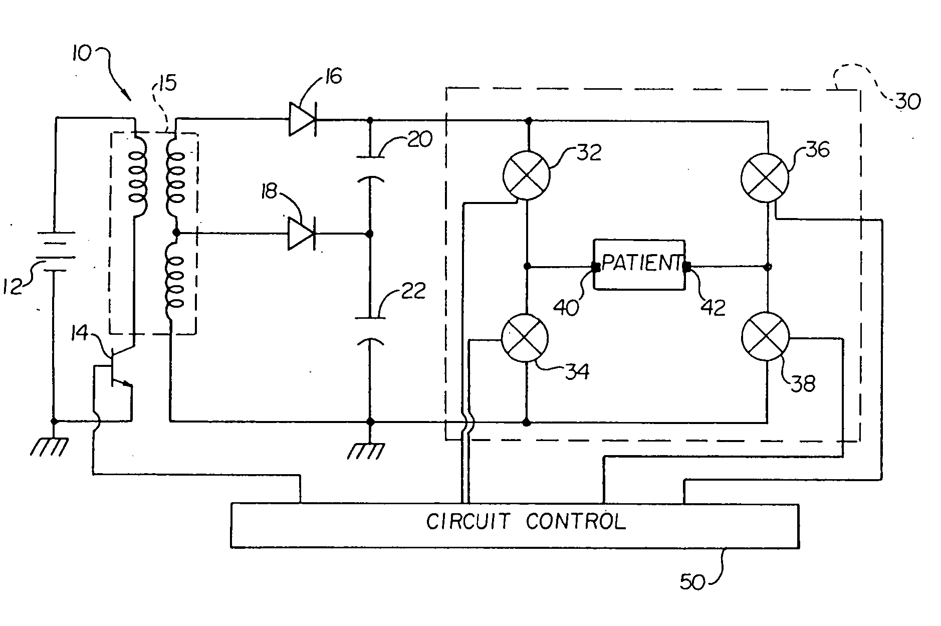
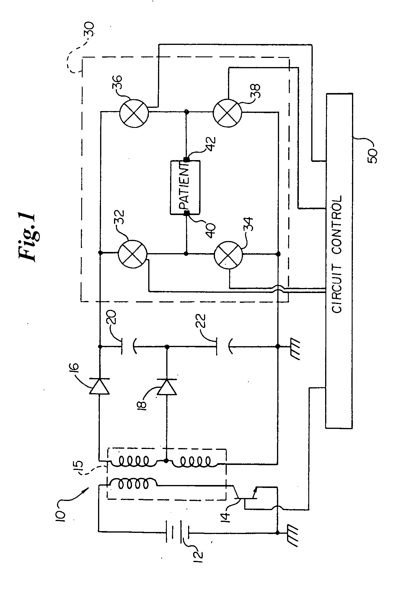
[0023] Referring first to FIG. 1, a schematic diagram of a typical ICD circuit including an H-bridge output circuit is illustrated. Circuit 10 includes a battery power source 12; a double secondary fly back transformer 15; a transistor switch 14; rectifying diodes 16, 18; high voltage storage capacitors 20, 22; circuit control 50; an output circuit 30 having four legs arranged in the form of an “H” (an “H-bridge 30”), each leg of the H-bridge 30 having switches 32, 34, 36, and 38, respectively; and cardiac electrodes 40, 42.

[0024] The H-bridge 30 is connected to cardiac electrodes 40, 42, and is used to generate a biphasic pulse. The H-bridge 30 switches the polarity of the two phases. A first phase is discharged from the high voltage storage capacitors 20, 22 by activating switches 32 and 38. Then the first phase is truncated, and the H-bridge 30 activates switches 36 and 34, and reverses the discharge polarity of the high voltage storage capacitors 20, 22 from the point of view o...


PUM


Abstract

In a cardioverter / defibrillator system, an electrical circuit includes an energy storage device, an output circuit for controlling delivery of pulse therapy from the energy storage device to a patient, and a sensing circuit coupled across the patient to sense the patient's heart signal. The output circuit may be in the form of an H-bridge switching circuit wherein a pair of switches of the output circuit is simultaneously turned on to discharge residual voltage across the patient that remains after delivery of pulse therapy. Thus, interference with sensing of the patient's heart signal is avoided.

Description

CROSS-REFERENCE TO CO PENDING AND RELATED APPLICATIONS [0001] This application is a continuation of co-pending U.S. application Ser. No. 10 / 011,946, filed Nov. 5, 2001, the disclosure of which is incorporated herein in its entirety. [0002] The present application may find use in systems such as are disclosed in the U.S. patent application entitled “SUBCUTANEOUS ONLY IMPLANTABLE CARDIOVERTER-DEFIBRILLATOR AND OPTIONAL PACER,” having Ser. No. 09 / 663,607, filed Sep. 18, 2000, now U.S. Pat. No. 6,721,597; and U.S. patent application entitled “UNITARY SUBCUTANEOUS ONLY IMPLANTABLE CARDIOVERTER-DEFIBRILLATOR AND OPTIONAL PACER,”; having Ser. No. 09 / 663,606, filed Sep. 18, 2000, now U.S. Pat. No. 6,647,292, of which both applications are assigned to the assignee of the present application, and the disclosures of both applications are hereby incorporated by reference. [0003] Applications related to the foregoing applications include a U.S. application Ser. No. 09 / 940,283, filed Aug. 27, 200...

Claims


Application Information

Patent Timeline
Patent Type & Authority Applications(United States)
IPC IPC(8): A61N1/39
CPCA61N1/3931A61N1/3912
Inventor RISSMANN, WILLIAM J.OSTROFF, ALAN H.
Owner CAMERON HEALTH
Why Eureka
Try Eureka