H-bridge with sensing circuit
a sensing circuit and hbridge technology, applied in the field of defibrillation/cardioversion systems, can solve the problems of no practical use, no use, and system is far more complicated to use, and achieve the effect of avoiding interference with the heart signal of the patien
- Summary
- Abstract
- Description
- Claims
- Application Information
AI Technical Summary
Benefits of technology
Problems solved by technology
Method used
Image
Examples
Embodiment Construction
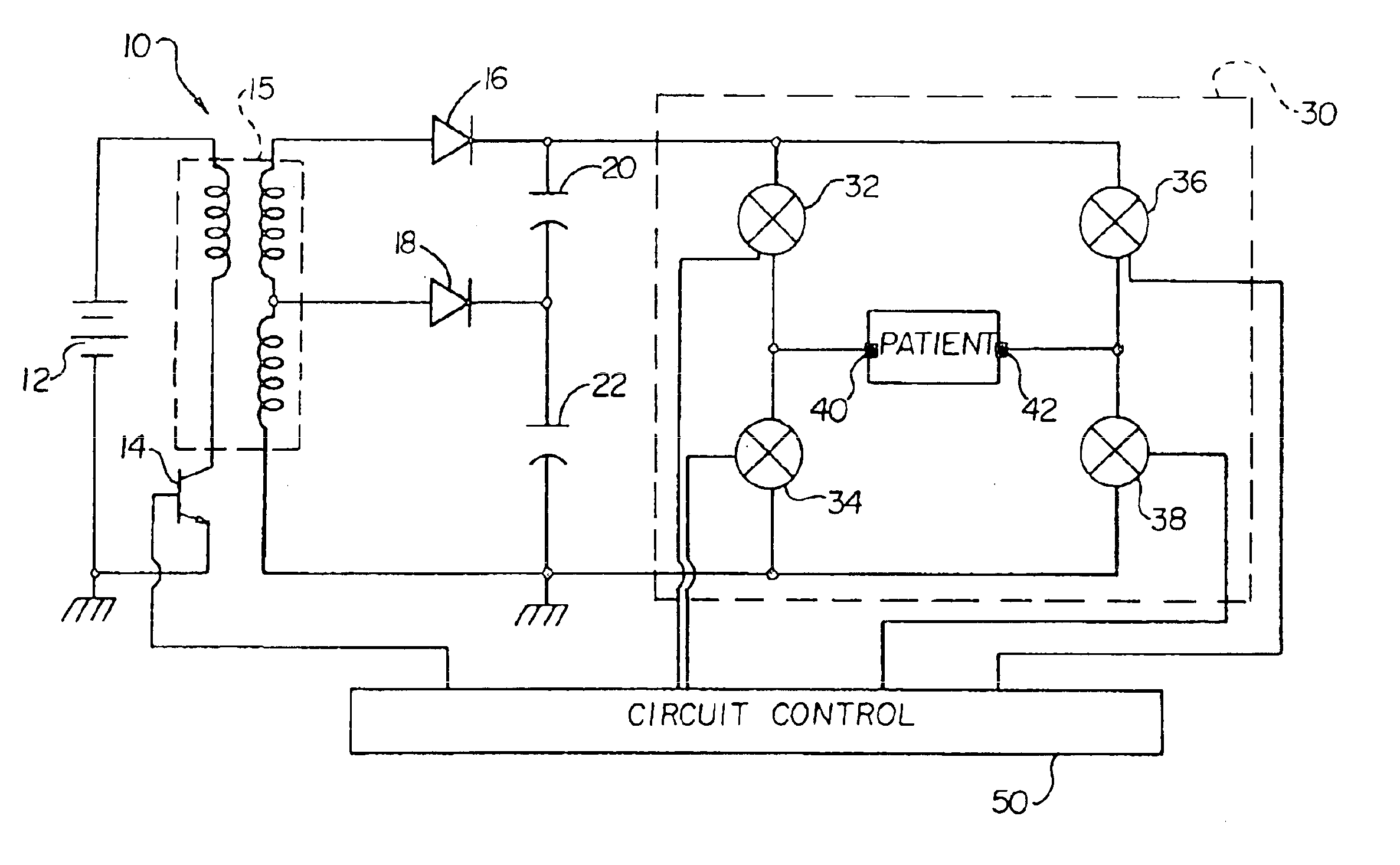
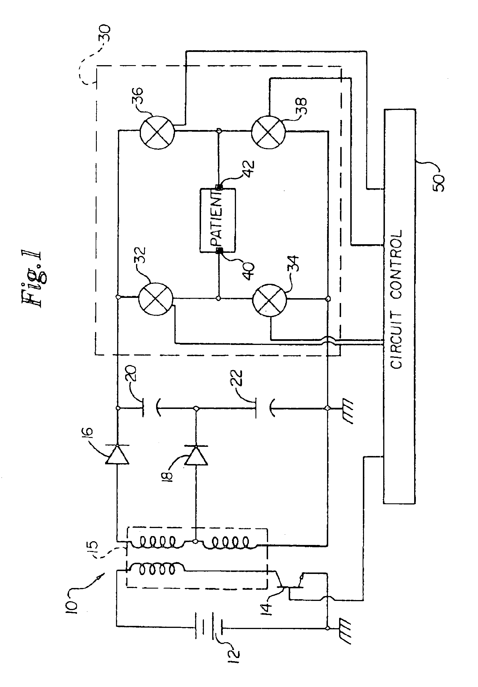
Referring first to FIG. 1, a schematic diagram of a typical ICD circuit including an H-bridge output circuit is illustrated. Circuit 10 includes a battery power source 12; a double secondary fly back transformer 15; a transistor switch 14; rectifying diodes 16, 18; high voltage storage capacitors 20, 22; circuit control 50; an output circuit 30 having four legs arranged in the form of an “H” (an “H-bridge 30”), each leg of the H-bridge 30 having switches 32, 34, 36, and 38, respectively; and cardiac electrodes 40, 42.
The H-bridge 30 is connected to cardiac electrodes 40, 42, and is used to generate a biphasic pulse. The H-bridge 30 switches the polarity of the two phases. A first phase is discharged from the high voltage storage capacitors 20, 22 by activating switches 32 and 38. Then the first phase is truncated, and the H-bridge 30 activates switches 36 and 34, and reverses the discharge polarity of the high voltage storage capacitors 20, 22 from the point of view of the cardiac e...
PUM
 Abstract
Description
Claims
Application Information
 - R&D
- Intellectual Property
- Life Sciences
- Materials
- Tech Scout
- Unparalleled Data Quality
- Higher Quality Content
- 60% Fewer Hallucinations
Browse by: Latest US Patents, China's latest patents, Technical Efficacy Thesaurus, Application Domain, Technology Topic, Popular Technical Reports.
© 2025 PatSnap. All rights reserved.Legal|Privacy policy|Modern Slavery Act Transparency Statement|Sitemap|About US| Contact US: help@patsnap.com


