
Motion-based hunting decoy

a motion-based, decoy technology, applied in the field of hunting decoys, can solve the problems of singleness, high cost of motorized systems, and high cost of motorized systems, and achieve the effects of increasing the cost of motion-based decoys, and increasing the cost of hunting decoys

Inactive Publication Date: 2005-06-23
FISHER TONY M
View PDF5 Cites 19 Cited by
  • Summary
  • Abstract
  • Description
  • Claims
  • Application Information

AI Technical Summary

Benefits of technology

[0008] Embodiments of the present invention solve one or more of the foregoing problems in the prior art with inexpensive, motion-based fowl decoy mechanisms. In particular, a conventional fowl decoy, as described herein, can be configured for natural movement, hence allowing a hunter to use motion-based decoys without incurring considerable costs.
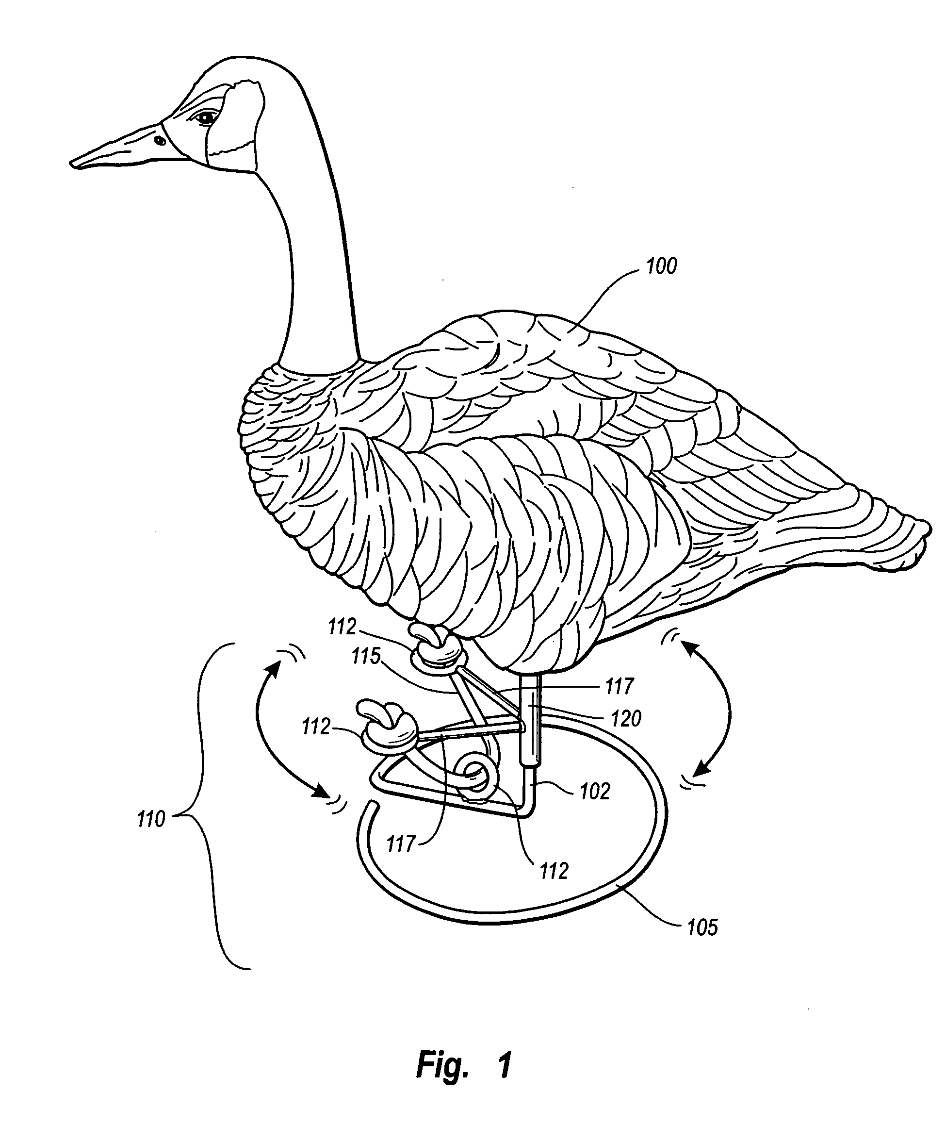
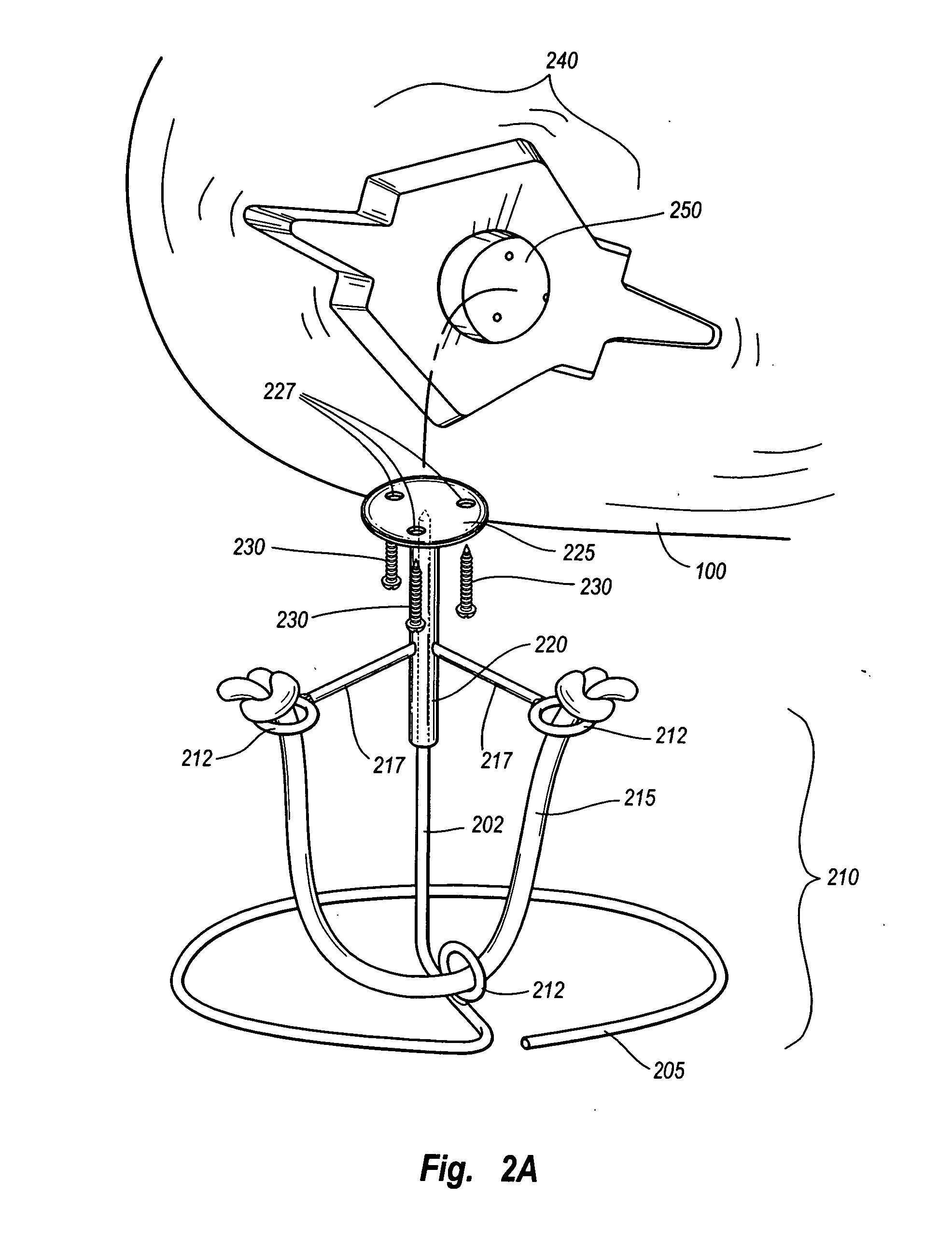
[0010] In one embodiment, the mounting assembly tilts somewhat about the support axis, particularly when the support axis' distal end forms a point. Thus, when the mounting assembly is connected to a decoy body, the inventive stand can give the decoy body a sense of up, down, side-to-side, and diagonal wobble. In addition, because the mounting assembly can rotate about the support axis, the mounting assembly can also provide the decoy body with a sense of natural side-to-side turning. Aspects of the present invention, therefore, provide a decoy with natural movement at a relatively low manufacturing expense.

Problems solved by technology

Unfortunately, if a fowl is sitting perfectly still in a single place, live fowl will still detect the decoy artifice, however realistic the color, shape, or flocking initially appears.
While motorized movement systems are generally more realistic than non-motorized counterparts in some cases, unfortunately, however, motorized systems are typically illegal.
Furthermore, motorized systems are also fairly expensive, which can be a particular problem for those who have already purchased motionless decoys.
By contrast, a single, motion-based decoy can cost as much as several hundreds of dollars alone, and can be even more expensive depending on the degree of realism provided by the intended movement.
Since hunters tend to prefer using multiple decoys for simulating a flock of fowl, one can appreciate that purchasing 10-12 motion-based decoys can therefore be prohibitively expensive.

Method used


Image

  • Motion-based hunting decoy
  • Motion-based hunting decoy
  • Motion-based hunting decoy

Examples


Embodiment Construction

[0016] Embodiments of the present invention include inexpensive, motion-based fowl decoy stands that can be implanted with conventional fowl decoys. Thus, a conventional fowl decoy, as described herein, can be configured for natural movement, hence allowing a hunter to use motion-based decoys without incurring considerable costs.

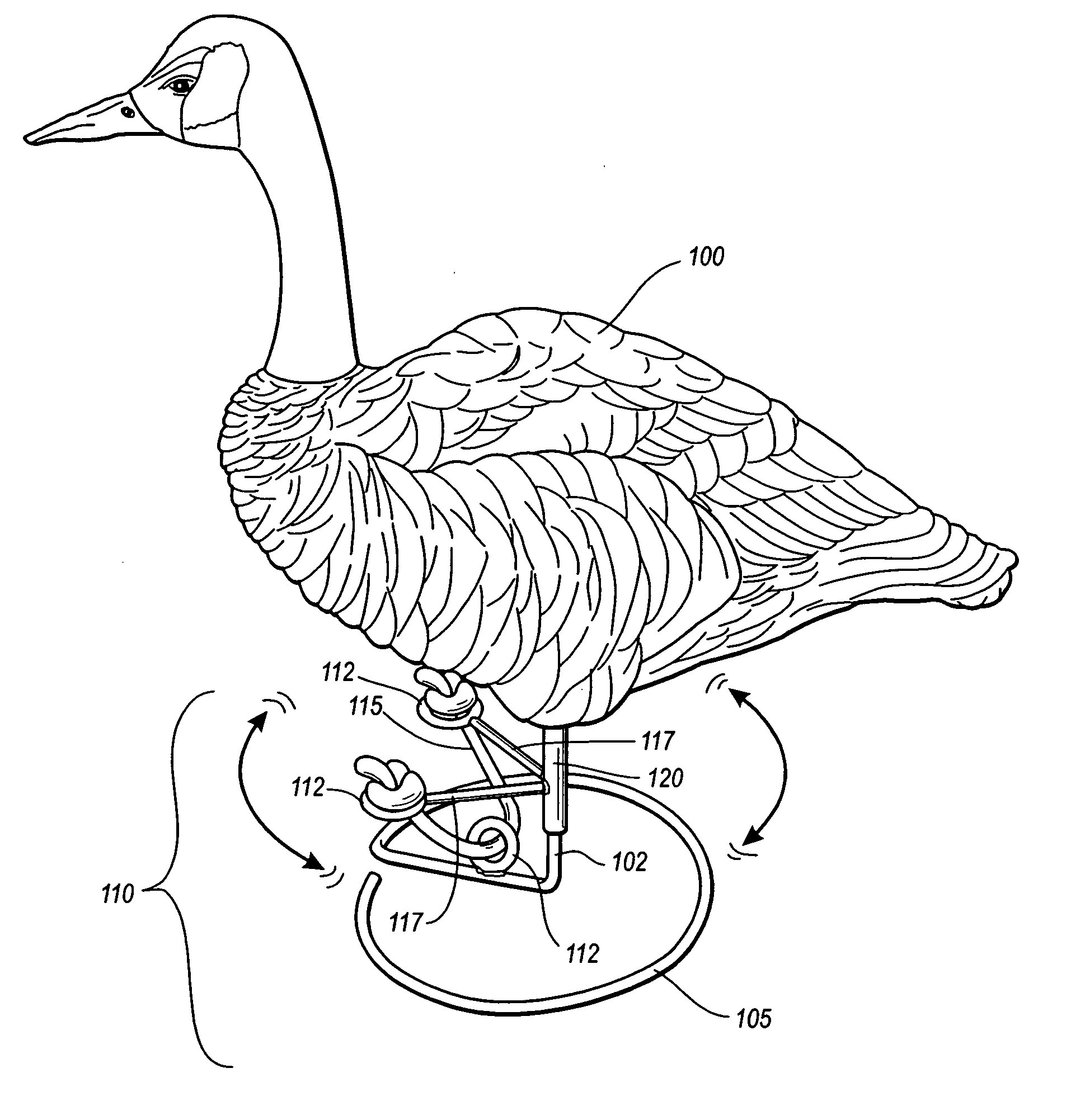
[0017]FIG. 1 illustrates an overview perspective of a fowl decoy that is configured to implement aspects of live fowl. In particular, the figure shows an exemplary implementation in which a fowl decoy 100 is mounted to a motion-based decoy stand 110. As will be discussed in greater detail herein, since the stand 110 is configured to give the decoy a certain amount of wobble and rotation, the stand 110 allows an otherwise motionless decoy to intimate live fowl movement.

[0018] As a preliminary matter, decoy 100 can be any conventional fowl decoy such as one that resembles a waterfowl, such as a duck or, goose, and any other type of fowl, such as a turkey, an...


PUM


Abstract

A motion-based decoy stand includes a base and a support axis extending from the base to a distal end. In one embodiment, the distal end can form a point. A mounting assembly includes an attachment interface and a hollow shaft connected to the attachment interface, the hollow shaft sliding about the support axis. The mounting assembly can be attached to a decoy where decoy legs would otherwise be present, and can allow the decoy to move with respect to the base. Mounting means and flexible restraints can be configured between the mounting assembly and the base to ensure the decoy moves within an expected range.

Description

BACKGROUND OF THE INVENTION [0001] 1. The Field of the Invention [0002] Embodiments of the present invention relate to hunting decoys. More specifically, the present invention relates to systems and methods that allow hunting decoys to simulate the movement of live fowl. [0003] 2. Background and Relevant Art [0004] Fowl that are looking for a place to rest and / or forage will generally prefer locations that other fowls have already chosen. In particular, fowl tend to be attracted to certain ground locations that the fowl sense is one of greater safety and / or nourishment. Accordingly, hunters looking to attract fowl will setup decoys at a certain location, such as a field, marsh, etc. In general, the decoys are chosen for exhibiting a certain quality, such as a look of realism, that gives live fowl a false perception that other fowl have found a place of safety, and / or nourishment. As such, the design quality of the hunter's decoys can have a significant impact on whether a hunter suc...

Claims


Application Information

Patent Timeline
IPC IPC(8): A01M31/06
CPCA01M31/06
Inventor FISHER, TONY M.
Owner FISHER TONY M
Learn More