Apparatus for weight heads assembly used on dumbbells

a technology of weight head and dumbbell, which is applied in the direction of weights, sport apparatus, gymnastics exercise, etc., can solve the problems of reducing the diameter, reducing the strength, and imposing a lot of pressure on the junction point between the stub portion and the central handle bar, and achieves the effect of reducing the cost of the mechanism

Active Publication Date: 2006-08-03
CAO GUOFANG
View PDF11 Cites 12 Cited by
  • Summary
  • Abstract
  • Description
  • Claims
  • Application Information

AI Technical Summary

Benefits of technology

[0005] Present invention provides an improved dumbbell assembly without causing a weakened portion of the handle bar, thus making the dumbbell more durable, and an inexpensive mechanism for securing the dumbbells in place.

Problems solved by technology

The problems with the common industry usage include, at least, first, tremendous pressure is exerted to the junction point between the stub portion (which has reduced diameter, thus reduced strength) and the central handle bar, and second, the high cost for the need to machined down the diameter of the stub to provide the hold pattern for the collars as well as the load-bearing portion that takes the weight head.

Method used


Image

  • Apparatus for weight heads assembly used on dumbbells
  • Apparatus for weight heads assembly used on dumbbells
  • Apparatus for weight heads assembly used on dumbbells

Examples


first embodiment

[0021]FIGS. 2-5 show present invention.

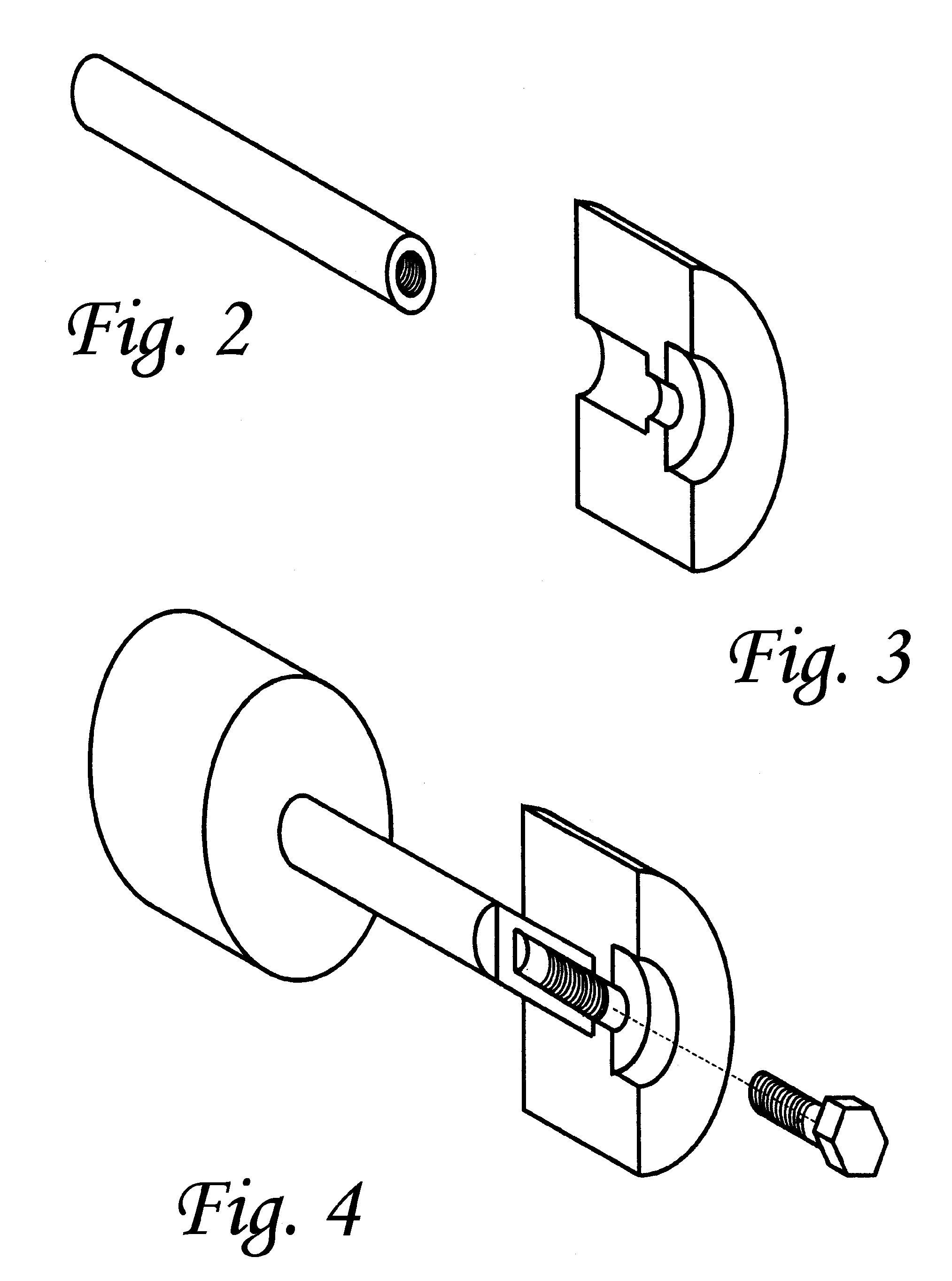
[0022]FIG. 2 shows a central handle bar having 2 non-through holes drilled in axially from the end. Thread lines are machined to the inside wall of said non-through holes. The handle bar's outside diameter remains the same throughout.

[0023]FIG. 3 and 4 show the cut-out view of the weight head, which has a through hole divided into 3 sections, having 3 respective diameter. The ‘stub’ portion of the weight head receives the ‘stub’ portion of the handle bar. A second section of the weight head's through hole is sized to receive a bolt with an attached locking nut. Finally, a third section of the through hole is sized to receive the capping piece of a tool, such as a wrench, when tightening or loosening the bolt to secure the weight head to the handle bar.

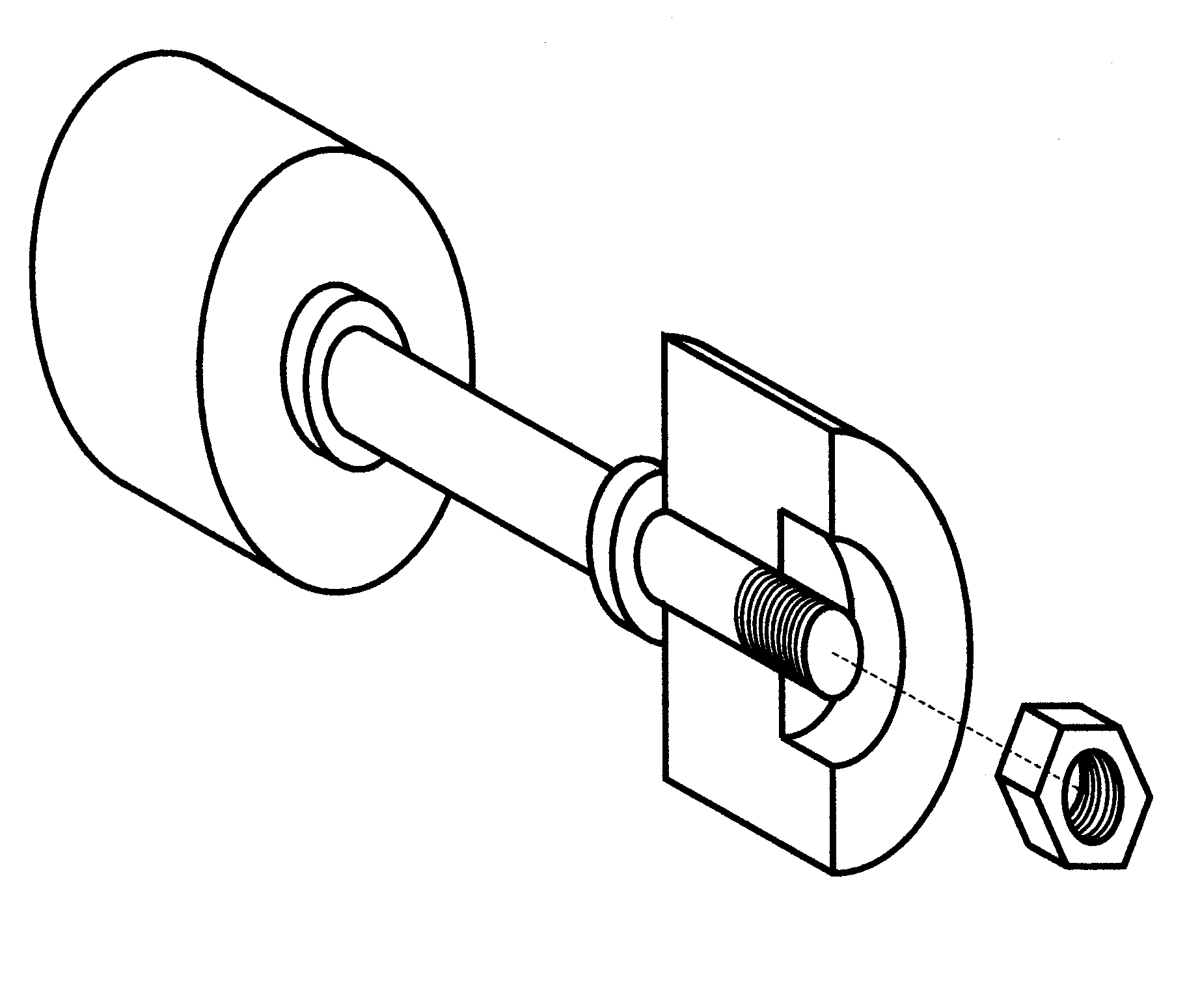
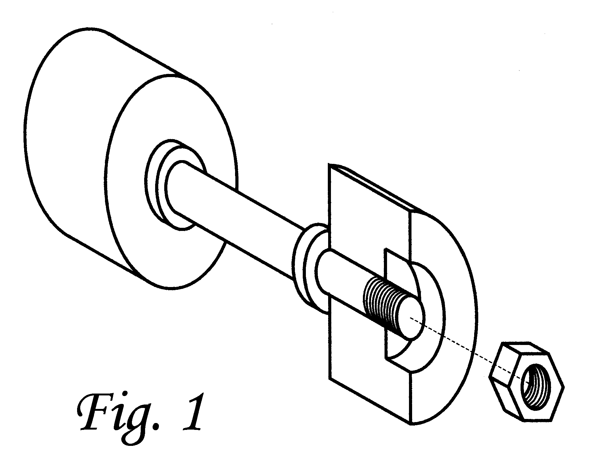
[0024]FIG. 5 shows a cut-out view of assembled weight head to the handle bar, as depicted by present invention.

second embodiment

[0025]FIGS. 6-9 show present invention.

[0026] In second embodiment, the bolt and the locking nut are separated. The end portion of the handle bar contains threads to receive locking nut. Like the first embodiment, the ‘stub’ portion on the handle bar remain the same diameter as the central portion of the handle bar, so that there will not be weak point in the load-bearing part of the handle bar.

[0027] The two end portions of the central handle bar will have machined threads to receive the locking nuts. To use the same weight head through hole configuration as in first embodiment, the threaded portion at two ends of the central handle bar will be machined down in diameter, as shown in FIGS. 6 and 8.

[0028] Alternatively, if the threaded portion on end portion of the handlebar is not machined down in diameter, as shown in FIGS. 10 and 11, then the weight head through hole configuration will consist of only 2 sections, one sized and threaded for receiving the ‘stub’ portion of the han...


PUM


Abstract

Weight head assembly for dumbbells that eliminates a weak point on the handle bar, so as to increase the durability of a handle bar on dumbbells. Under present invention, the ‘stub’ portion, where the handlebar is inserted into the weight heads on the two ends of the bar, need not be machined own in size, and can thus withstand more wear and tear for regular usage in fitness training. The cost of manufacturing the handle bar, and as a result of the increase durability, will help the fitness industry greatly when making new dumbbells.

Description

FIELD AND BACKGROUND OF THE INVENTION [0001] The present invention relates generally to design and construction of dumbbell weight heads assembly used on fitness training equipment. [0002] Traditional dumbbells have a handle bar with two ends attaching to the bells, or called weight heads. [0003] To prevent the two dumbbells from sliding towards the center of the handle bar, two collars are commonly used for this purpose. The load-bearing portion (called ‘stub’) on the two ends of the handle bar is usually machined down to reduce the diameter so that the collars would properly be ‘pinched’ in place and serve to prevent the dumbbells from sliding towards the center of the handle bar. See FIG. 1, showing prior art industry usage. [0004] The problems with the common industry usage include, at least, first, tremendous pressure is exerted to the junction point between the stub portion (which has reduced diameter, thus reduced strength) and the central handle bar, and second, the high cos...

Claims


Application Information

Patent Timeline
Patent Type & Authority Applications(United States)
IPC IPC(8): A63B21/072A63B21/075
CPCA63B21/075
Inventor CAO, GUOFANG
Owner CAO GUOFANG
Why Eureka
Try Eureka