Drive device, and movement mechanism using drive device

a technology of driving device and movement mechanism, which is applied in the direction of propulsion system, electrical apparatus, dynamo-electric machines, etc., can solve the problems of troublesome parts management and assembly tasks, and achieve the effect of compact, lightweight and inexpensive movement mechanism, compact, and simpl

Inactive Publication Date: 2013-01-10
SANYO ELECTRIC CO LTD
View PDF4 Cites 0 Cited by
  • Summary
  • Abstract
  • Description
  • Claims
  • Application Information

AI Technical Summary

Benefits of technology

[0007]The present invention is to solve the above problems, and an object of the present invention is to provide a drive device which can achieve a reciprocating movement and a movement mechanism using the drive device with a compact, simple, and inexpensive configuration.
[0014]According to the drive device of the present invention, since groups of the electric conductor and the electromagnetic coil are provided each on the both sides of the elastic body, using each of the groups properly, a reciprocating movement of the object-to-be-moved can be achieved by only one drive device. According to the above drive device, a downsized, lightweight, and inexpensive movement mechanism can be achieved. Moreover, since the drive device has the symmetrical configuration in both directions of the reciprocating movement, a symmetrical impact can be generated, and a drive control using the above configuration can easily be achieved.
[0015]Moreover, according to the movement mechanism of the present invention, an XY table, a rectilinear movable table, a XYθ table, a gimbal structure which controls an inclination angle, a rotation angle, or the like of a moving object, or the like can be achieved with a compact, simple, and inexpensive configuration without using a motor, a driving force transmission device such as a ball screw, or the like.

Problems solved by technology

However, the drive device described in the above patent documents 1 to 3 can only generate the impact in one side (aspect or sense) of a direction using one drive device, and therefore two drive devices are required to reciprocate the object.
Thus, a movement mechanism in which an object is reciprocated by such a drive device has problems that a downsizing of the device is restricted and an increased number of the drive devices causes troublesome tasks for parts management and assembly.

Method used


Image

  • Drive device, and movement mechanism using drive device
  • Drive device, and movement mechanism using drive device
  • Drive device, and movement mechanism using drive device

Examples


first embodiment

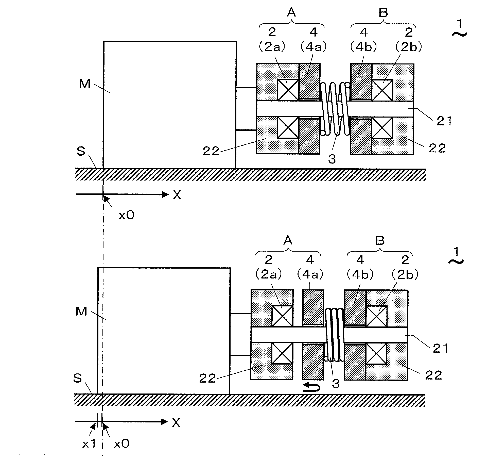
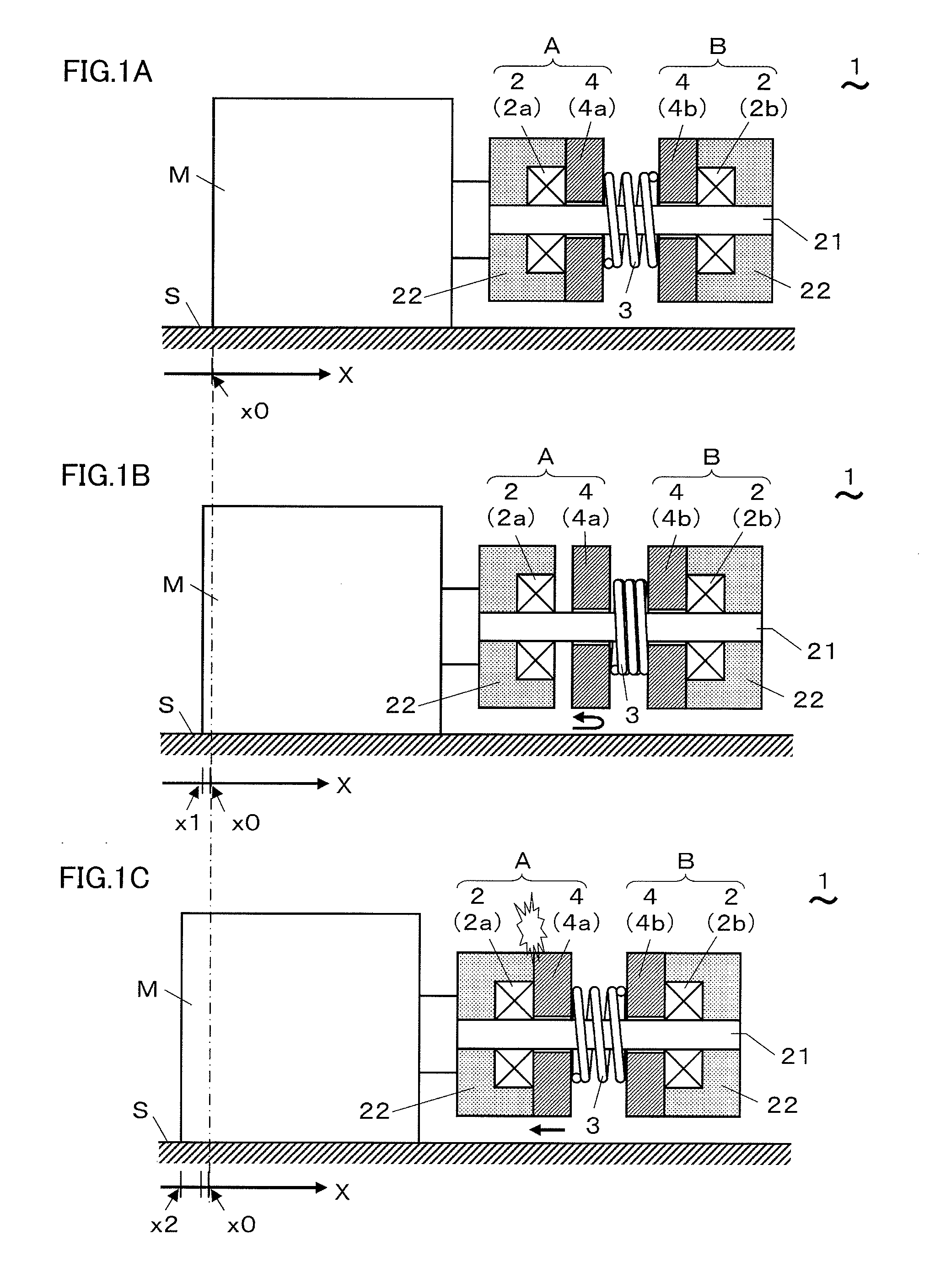
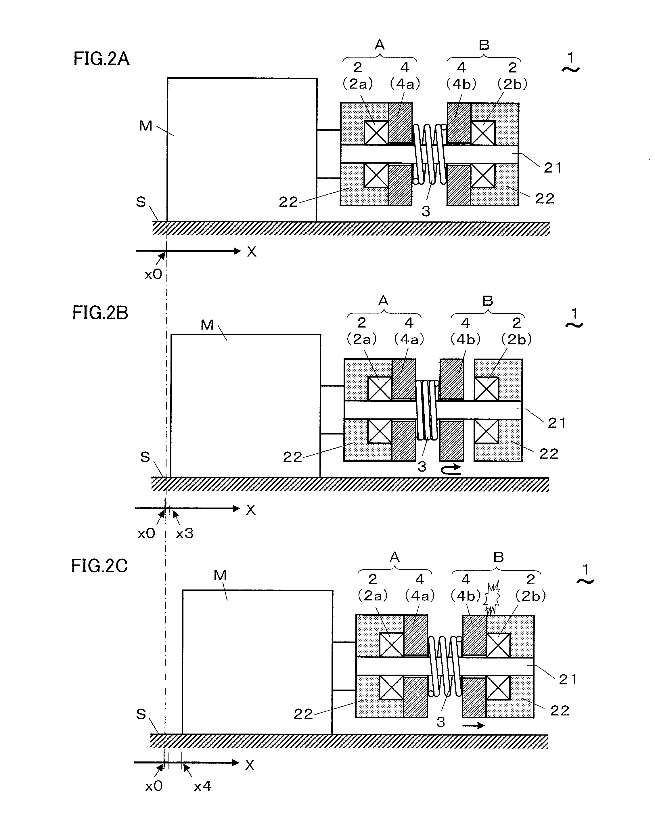
[0031]A drive device and a movement mechanism using the drive device according to embodiments of the present invention are described with reference to the drawings. FIGS. 1A, 1B, 1C, 2A, 2B, and 2C show a drive device according to the first embodiment. As shown in FIG. 1A, a drive device 1 includes first and second electromagnetic coils 2a and 2b (also referred to as an electromagnetic coil 2 collectively), an elastic body 3, and first and second electric conductors 4a and 4b (also referred to as an electric conductor 4 collectively) located coaxially each other. The first and second electromagnetic coils 2a and 2b are separately, coaxially and oppositely located each other, and are integrated with each other. The elastic body 3 is located between the first and second electromagnetic coils. The first electric conductor 4a is located between the first electromagnetic coil 2a and the elastic body 3, and the second electric conductor 4b is located between the second electromagnetic coi...

second embodiment

[0040]FIGS. 9A to 9C show a movement mechanism according to the second embodiment. As shown in FIG. 9A, a movement mechanism 11 of the present embodiment includes a base table M0, a first moving table M1, a second moving table M2, and drive means 1x and 1y. The first moving table M1 is supported by the base table M0 and is movable along the X axis direction. The second moving table M2 is supported by the moving table M1 and is movable along the Y axis direction perpendicular to the X axis direction. The drive means 1x and 1y drive and move the first and second moving tables M1 and M2, respectively. In the movement mechanism 11, the drive device 1 according to any of the above first embodiment 1 and the modification examples of the first embodiment 1 is used as the drive means 1x and 1y. The movement mechanism 11 is made by putting one linear motion guide on top of another linear motion guide in X and Y directions, respectively, and makes up an XY table.

[0041]The support of the first...

modification example

of the Second Embodiment

[0042]FIGS. 10A, 10B, and 11 show a modification example of the movement mechanism according to the second embodiment. A movement mechanism 12 in FIG. 10A includes a moving table M3 of a flat plate shape used placing on a flat friction surface and a drive means 1x which generates a driving force along an X axis direction parallel to the friction surface. In the movement mechanism 12, the drive device 1 according to any of the above first embodiment 1 and the modification examples of the first embodiment 1 is used as the drive means 1x. Moreover, a movement mechanism 12 in FIG. 10B further includes a drive means 1y which generates a driving force in a Y axis direction parallel to the friction surface and perpendicular to the X axis direction, in addition to the movement mechanism 12 in FIG. 10A. In the same manner as the drive means 1x, the drive device 1 according to any of the above first embodiment 1 and the modification examples of the first embodiment 1 i...


PUM


Abstract

A drive device includes two integrated electromagnetic coils separated on an axis, an elastic body, and two movable electric conductors. An object-to-be-moved is moved to left with an operation of a left group which includes one electromagnetic coil and one conductor. A first conductor is repulsively moved to right by a repulsion force caused by an eddy current generated on the first conductor with an electrical current-supply to a first electromagnetic coil and then, the elastic body is compressed by the first conductor and subsequently pushes back the first conductor. At this time, the electrical current-supply to the first electromagnetic coil is turned off, and the first conductor collides with the first electromagnetic coil, and this collision generates a leftward impact. The left and right groups enable a left-right reciprocating movement.

Description

TECHNICAL FIELD [0001]The present invention relates to a drive device using an electromagnetic action and a movement mechanism using the drive device.BACKGROUND ART [0002]Conventionally, there is a drive device which repeatedly provides a shock, that is to say, an impact, caused by an electromagnetic action to an object and moves the object. Even the small impact enables the movement of the object when being provided repeatedly, and moreover, it also has an advantage that it enables a high-accuracy position control. There is a known method of using an electrostrictive element or an eddy current to generate the impact (refer to patent documents 1 and 2, for example). The eddy current is a current which circularly flows in a metal plate such as an aluminum plate, for example, when a current flows in an electromagnetic coil which is located close to the metal plate. When an impulse current flows in the electromagnetic coil, a repulsion force which bounces the metal plate off occurs by ...

Claims


Application Information

Patent Timeline
Patent Type & Authority Applications(United States)
IPC IPC(8): H02K41/02
CPCH02K33/16H02K33/12
Inventor FUJIWARA, SHIGEKIISHIGAMI, YOUHEIMITSUTAKE, YOSHIOSUZUKI, SATOSHI
Owner SANYO ELECTRIC CO LTD
Why Eureka
Try Eureka