Drive device, and movement mechanism using drive device

Inactive Publication Date: 2013-02-14
SANYO ELECTRIC CO LTD
View PDF1 Cites 18 Cited by
  • Summary
  • Abstract
  • Description
  • Claims
  • Application Information

AI Technical Summary

Benefits of technology

The present invention provides a drive device that can achieve a reciprocating movement and a movement mechanism using the drive device with a compact, simple, and inexpensive configuration. The drive device is made by combining the permanent magnet and the stopper with one electromagnetic coil, which allows for a compact and simple configuration. The movement mechanism can achieve an XY table, a rectilinear movable table, a XYθ table, a gimbal structure which controls an inclination angle, a rotation angle, or the like with a compact, simple, and inexpensive configuration.

Problems solved by technology

However, the drive device described in the above patent documents 1 to 3 can only generate the impact in one side (aspect or sense) of a direction using one drive device, and therefore two drive devices are required to reciprocate the object.
Thus, a movement mechanism in which an object is reciprocated by such a drive device has problems that a downsizing of the device is restricted and an increased number of the drive devices causes troublesome tasks for parts management and assembly.

Method used


Image

  • Drive device, and movement mechanism using drive device
  • Drive device, and movement mechanism using drive device
  • Drive device, and movement mechanism using drive device

Examples


first embodiment

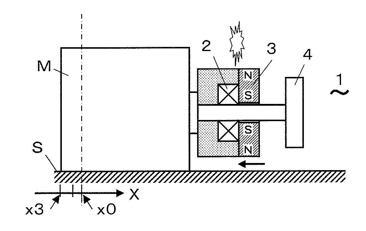
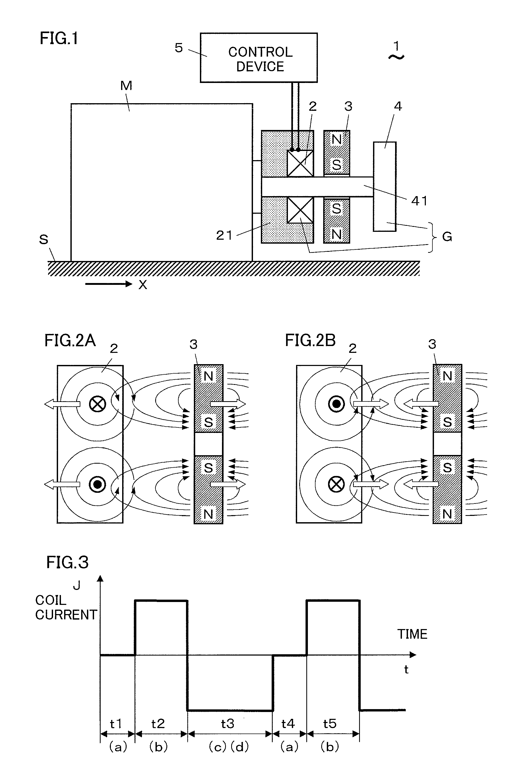
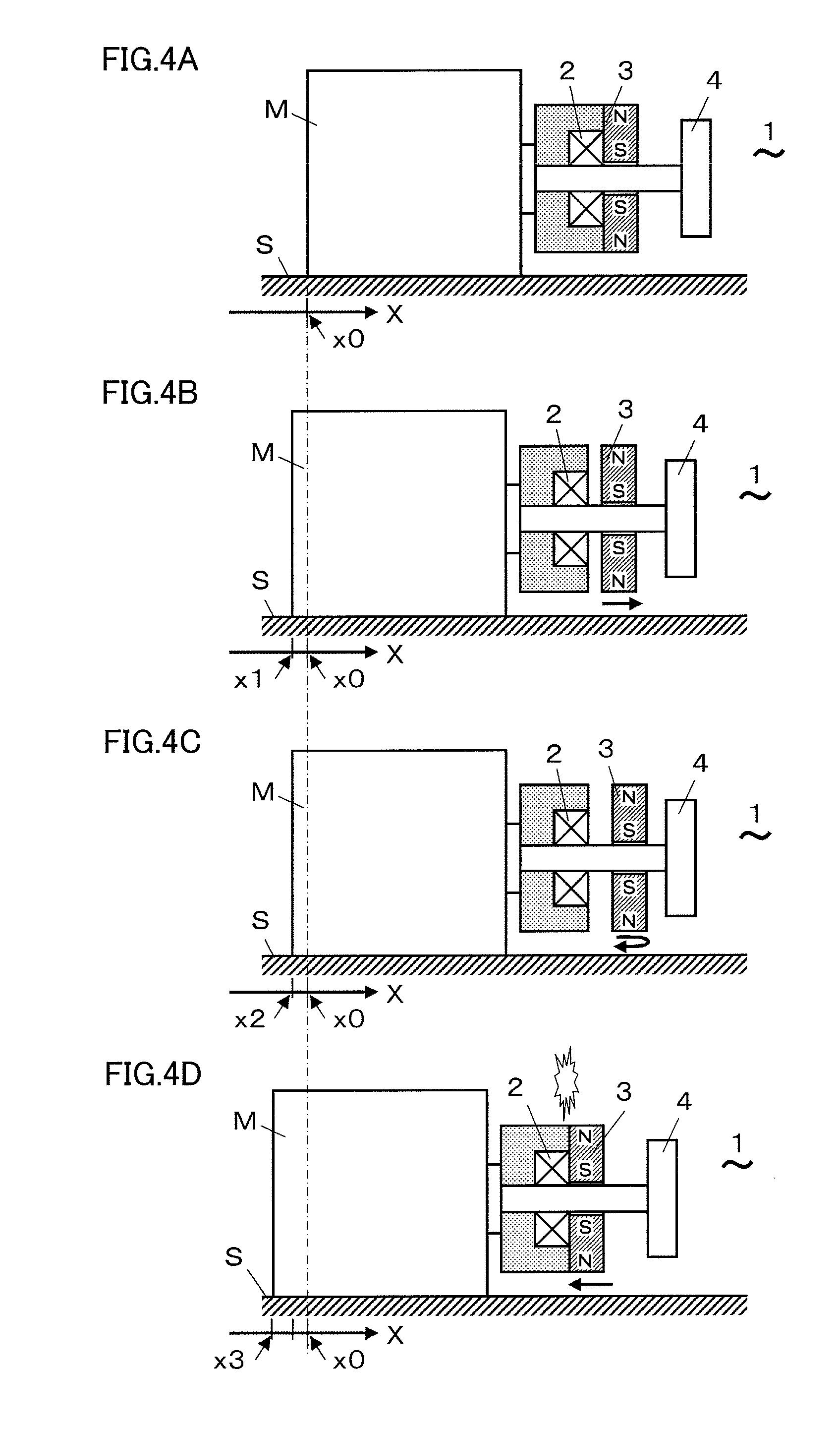
[0045]A drive device and a movement mechanism using the drive device according to embodiments of the present invention are described with reference to the drawings. FIGS. 1 to 6F show a drive device according to the first embodiment. As shown in FIG. 1, a drive device 1, which provides an impact to an object-to-be-moved M and moves the object-to-be-moved M, includes an electromagnetic coil 2, a permanent magnet 3, a stopper 4, and a control device 5. The permanent magnet 3 relatively moves relative to the electromagnetic coil 2 by an electromagnetic action caused by an electrical current-supply to the electromagnetic coil 2. The stopper 4 is integrated with the electromagnetic coil 2 to form a collided-body G so that a range of the relative movement of the permanent magnet 3 is restricted. The control device 5 temporally controls an electrical current supplied to the electromagnetic coil 2. When the electrical current is supplied to the electromagnetic coil 2 in the drive device 1, ...

second embodiment

[0057]FIGS. 17A to 17C show a movement mechanism according to the second embodiment. As shown in FIG. 17A, a movement mechanism 11 of the present embodiment includes a base table M0, a first moving table M1, a second moving table M2, and drive means 1x and 1y. The first moving table M1 is supported by the base table M0 and is movable along the X axis direction. The second moving table M2 is supported by the moving table M1 and is movable along the Y axis direction perpendicular to the X axis direction. The drive means 1x and 1y drive and move the first and second moving tables M1 and M2, respectively. In the movement mechanism 11, the drive device 1 according to any of the above first embodiment 1 and the modification examples of the first embodiment 1 is used as the drive means 1x and 1y. The movement mechanism 11 is made by putting one linear motion guide on top of another linear motion guide in X and Y directions, respectively, and makes up an XY table.

[0058]The support of the fi...

modification example

of the Second Embodiment

[0059]FIGS. 18A to 19 show a modification example of the movement mechanism according to the second embodiment. A movement mechanism 12 in FIG. 18A includes a moving table M3 of a flat plate shape used placing on a flat friction surface and a drive means 1x which generates a driving force along an X axis direction parallel to the friction surface. In the movement mechanism 12, the drive device 1 according to any of the above first embodiment 1 and the modification examples of the first embodiment 1 is used as the drive means 1x. Moreover, the movement mechanism 12 in FIG. 18B further includes a drive means 1y which generates a driving force in a Y axis direction parallel to the friction surface and perpendicular to the X axis direction, in addition to the movement mechanism 12 in FIG. 18A. In the same manner as the drive means 1x, the drive device 1 according to any of the above first embodiment 1 and the modification examples of the first embodiment 1 is use...


PUM


Abstract

A drive device which provides an electromagnetic impact and a movement mechanism using the drive device to achieve a reciprocating movement with a compact and simple configuration. A drive device provides an impact to an object-to-be-moved supported by a friction surface and moves the object-to-be-moved, and includes an electromagnetic coil, a permanent magnet, a stopper, and a control device which controls the electromagnetic coil. The permanent magnet relatively moves to the electromagnetic coil by an action caused by an electrical current supply to the electromagnetic coil. When the electrical current is supplied to the electromagnetic coil, the permanent magnet collides with the electromagnetic coil or the stopper, which forms the collided-body, and generates the impact. The impact can be generated in any direction, then a reciprocating movement of the object-to-be-moved can be achieved.

Description

TECHNICAL FIELD[0001]The present invention relates to a drive device using an electromagnetic action and a movement mechanism using the drive device.BACKGROUND ART[0002]Conventionally, there is a drive device which repeatedly provides a shock, that is to say, an impact, caused by an electromagnetic action to an object and moves the object. Even the small impact enables the movement of the object when being provided repeatedly, and moreover, it also has an advantage that it enables a high-accuracy position control. There is a known method of using an electrostrictive element or an eddy current to generate the impact (refer to patent documents 1 and 2, for example). The eddy current is a current which circularly flows in a metal plate such as an aluminum plate, for example, when a current flows in an electromagnetic coil which is located close to the metal plate. When an impulse current flows in the electromagnetic coil, a repulsion force which bounces the metal plate off occurs by an...

Claims


Application Information

Patent Timeline
IPC IPC(8): H02K33/16H02K33/18
CPCH02K33/16H01F7/066H01F7/1646H01F7/14H01F7/122
Inventor FUJIWARA, SHIGEKIISHIGAMI, YOUHEIMITSUTAKE, YOSHIOSUZUKI, SATOSHI
Owner SANYO ELECTRIC CO LTD
Why Eureka
Try Eureka