Method for establishing a communication on a standby link in optical transmission facilities

Inactive Publication Date: 2005-01-04
NOKIA SIEMENS NETWORKS GMBH & CO KG
View PDF8 Cites 8 Cited by
  • Summary
  • Abstract
  • Description
  • Claims
  • Application Information

AI Technical Summary

Benefits of technology

The criteria which trigger a protection switchover are also used for laser safety switch-off. The method, which is simple to achieve, provides for reliable identification of an absent useful signal. In the case of the present invention, even if the laser/amplifier for the useful signal to be transmitted is switched off in one terminal, control signals continue to be transmitted with a permissible level to the corresponding terminal. This makes it possible for the system to be switched on anew or switched on again without the monitoring mode having to be deactivated. The energy in the monitoring channel is dimensioned to preclude any danger to engineers performing repair work.
Via the monitoring chann

Problems solved by technology

Additional problems also arise in the context of optical transmission by means of wavelength division multiplex te

Method used


Image

  • Method for establishing a communication on a standby link in optical transmission facilities
  • Method for establishing a communication on a standby link in optical transmission facilities
  • Method for establishing a communication on a standby link in optical transmission facilities

Examples


Example

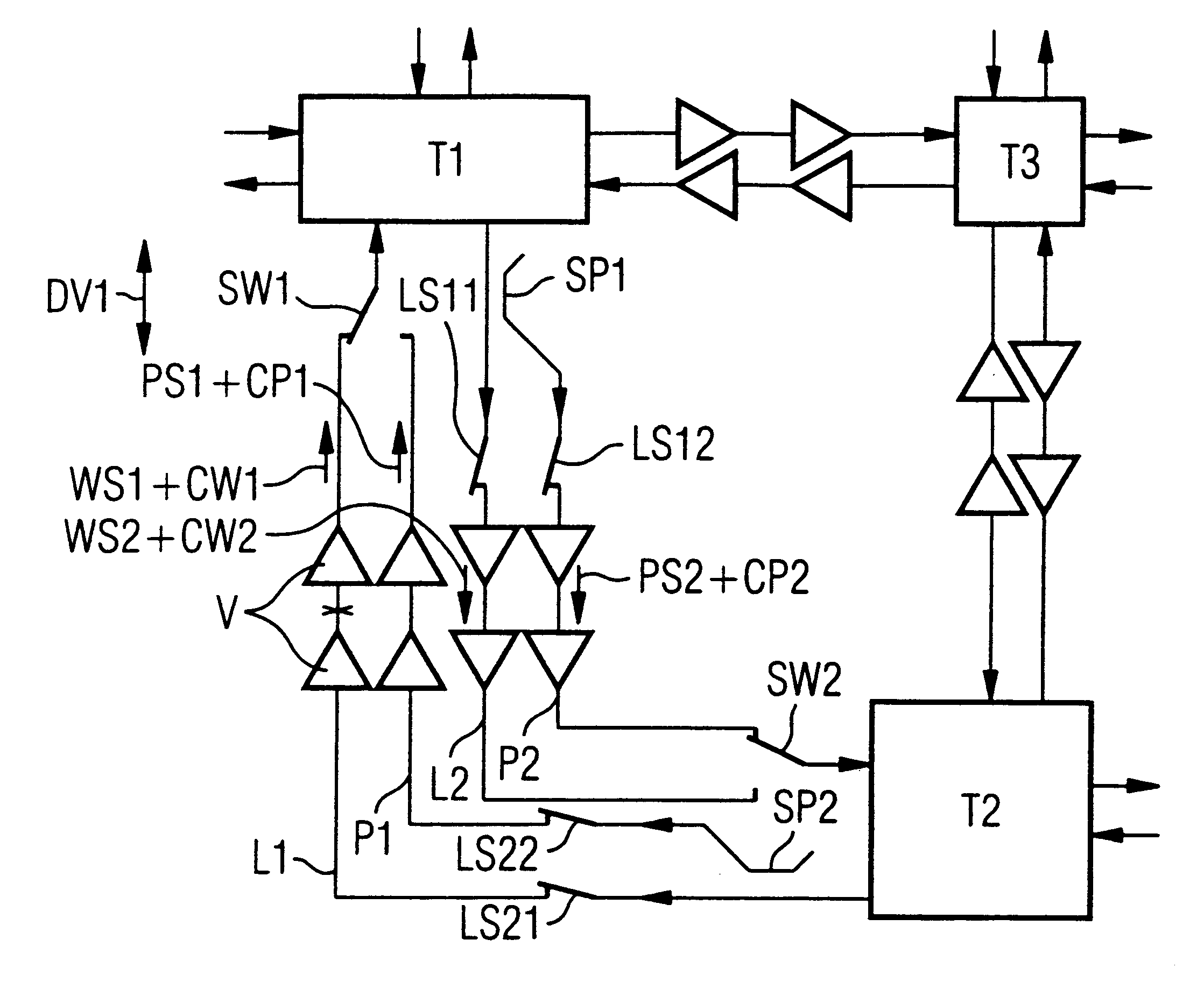
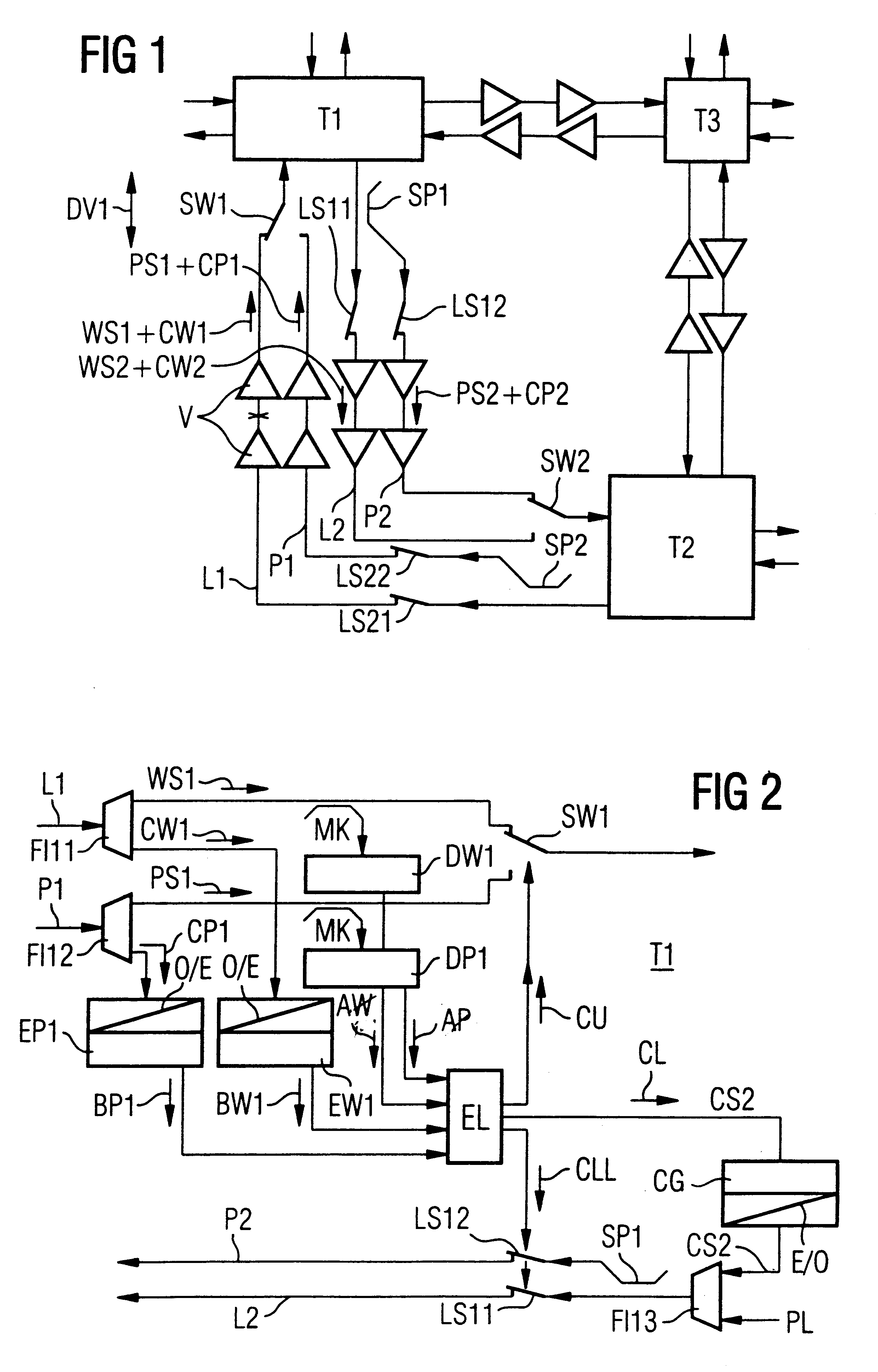
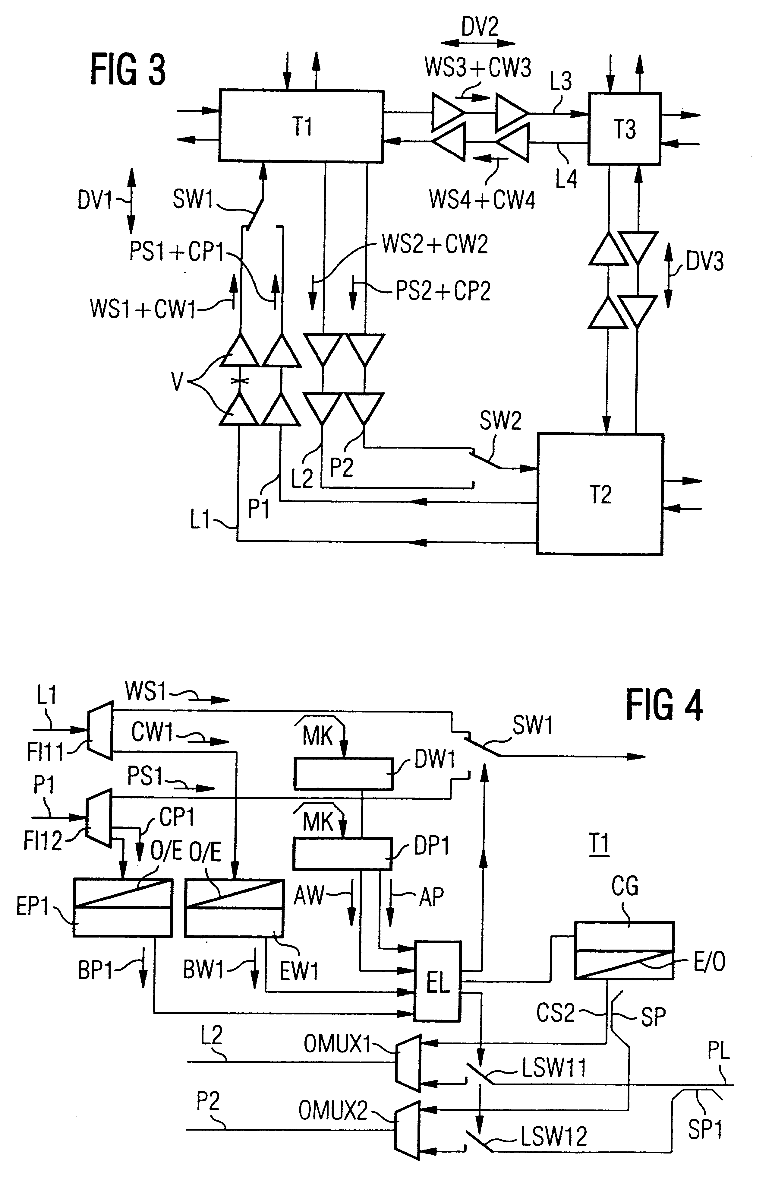
FIG. 1 shows the part of a transmission network with three terminals T1 to T3. Of this, the connection DV1 between the terminals T1 and T2 will initially be considered in greater detail. A first working signal WS1 is transmitted via a first working optical fiber L1 from the terminal T2, which is a cross-connector, for example, to the terminal T1. At the same time, an identical protection signal PS1 is transmitted via a second optical fiber, the protection optical fiber P1. Each of these signals may include one or more signal elements which are each assigned a wavelength. In addition, a control signal CS1, CP1 (or a number of control signals) is transmitted via a respective monitoring channel. The signal contains, inter alia, allocation information specifying whether at least one signal element is being transmitted (or no signal is being transmitted). In alternative embodiments, the number of signal elements which are present or absent can be specified.

In the opposite direction, a wo...


PUM


Abstract

A method for standby switching in optical transmission devices is provided, wherein, in addition to a working signal and a protection signal, respective control signals with information concerning the allocation state are transmitted and evaluated at the receiving end. The control signals are transmitted via a monitoring channel even when the useful signal is switched off.

Description

BACKGROUND OF THE INVENTIONIn optical transmission networks, in the event of disturbances to a connection, a so-called protection connection is switched via another transmission path. For ring networks, instances of such standby switching are described, for example, in “26th European Conference On Optical Communication ECOC 96, Oslo, pages 3.51 to 3.54”. In the so-called “hot standby” mode, the same message is continuously transmitted in parallel via additional protection data paths, so that a switchover can be effected without a time delay in the event of a disturbance.Additional problems also arise in the context of optical transmission by means of wavelength division multiplex technology, which problems make it more difficult to identify a line breakage or other failure of the useful signal. For safety reasons, the optical transmission signal is switched off in the event of a disturbed connection; for example, by the laser or an optical amplifier connected downstream being switch...

Claims


Application Information

Patent Timeline
IPC IPC(8): H04B10/00H04B10/08H04B10/032H04B10/077
CPCH04B10/032H04B10/077H04B10/0773H04J14/0295H04J14/0289H04B2210/077H04B2210/078H04J14/0283H04J14/0291H04J14/0294H04B2210/08
Inventor JAHREIS, OLIVERHEILES, JURGEN
Owner NOKIA SIEMENS NETWORKS GMBH & CO KG
Why Eureka
Try Eureka