
Electronic circuit breaker with lockout mechanism integrated into electronic trip mechanism

a technology of electronic circuit breakers and lockout mechanisms, which is applied in the direction of earth fault current operated switches, operating/releasing mechanisms of protective switches, electrical equipment, etc., can solve the problems of not being able to achieve the economic approach of building a lockout breaker, bringing the margin down significantly, and not working properly to provide intended electrical protection. , to achieve the effect of less electromagnets

Active Publication Date: 2021-02-23
SIEMENS IND INC
View PDF4 Cites 0 Cited by
  • Summary
  • Abstract
  • Description
  • Claims
  • Application Information

AI Technical Summary

Benefits of technology

The present invention is about an economical lockout mechanism for an electronic circuit breaker. It uses a single electromagnet instead of three magnets, which saves money and reduces the cost of the circuit breaker. This makes it a more cost-effective option for those who need a lockout feature for their circuit breaker.

Problems solved by technology

If an electronic component is damaged or failed, the electronics may not work properly to provide the intended electrical protection.
However, this is not an economical approach to build a lockout breaker, since it uses a lot of electromagnets, which are costly components in a circuit breaker.
Incorporating a lockout mechanism inside a circuit breaker this way brings the margin down significantly.
Usually, most electronic circuit breakers do not even have lockout mechanism, since it costs a lot of money and lockout mechanism is currently not a safety requirement.
However, use of such a bimetal is not the best solution.

Method used


Image

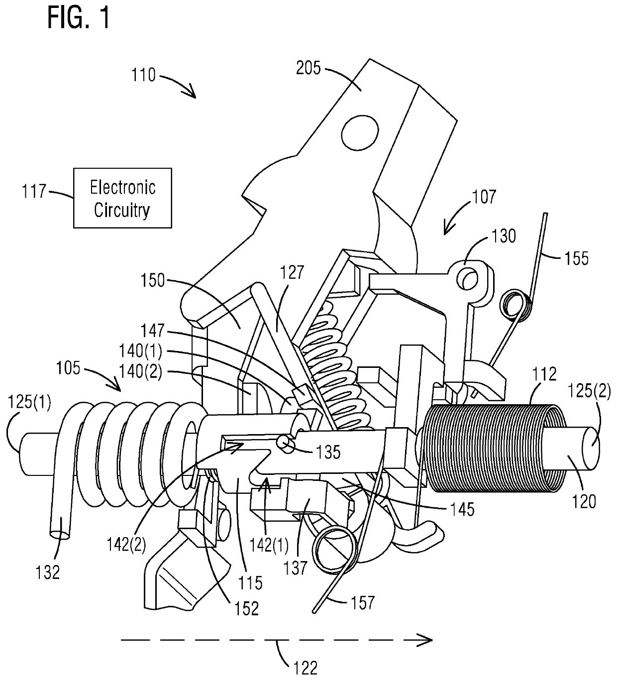
  • Electronic circuit breaker with lockout mechanism integrated into electronic trip mechanism
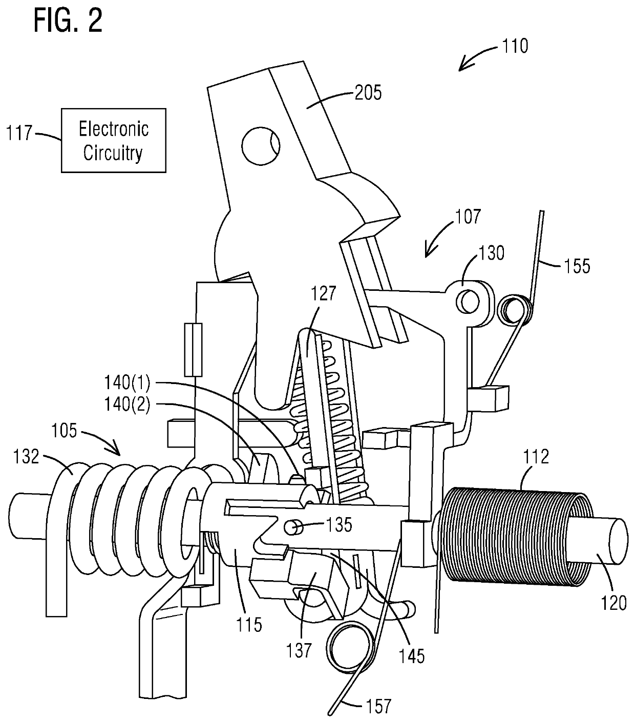
  • Electronic circuit breaker with lockout mechanism integrated into electronic trip mechanism
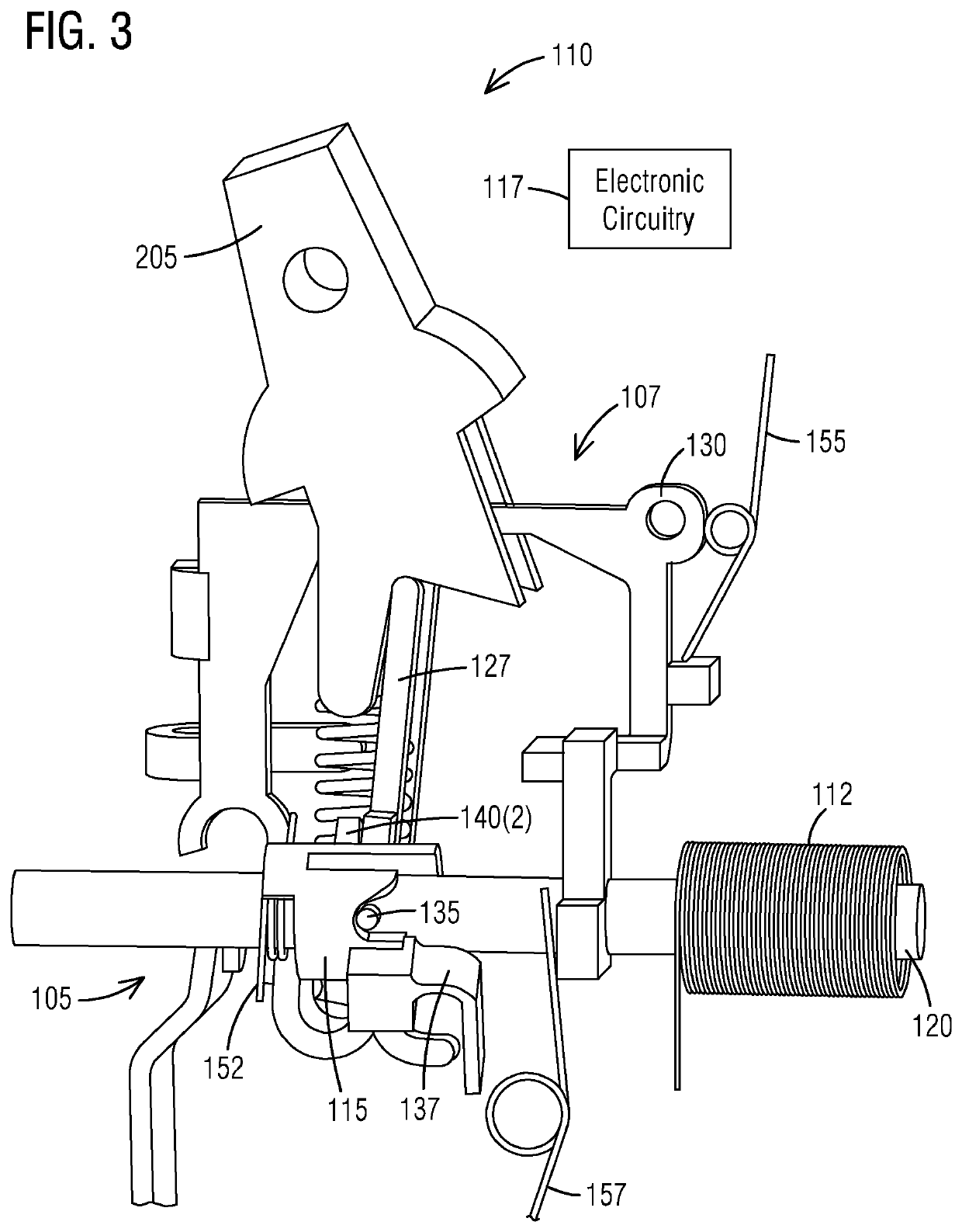
  • Electronic circuit breaker with lockout mechanism integrated into electronic trip mechanism

Examples


Embodiment Construction

[0015]To facilitate an understanding of embodiments, principles, and features of the present invention, they are explained hereinafter with reference to implementation in illustrative embodiments. In particular, they are described in the context of a lockout circuit breaker consisted of a lockout mechanism that is integrated into an electronic trip mechanism using a single electromagnet and a barrel. The lockout mechanism is used in the lockout circuit breaker to lock the breaker from being able to be turned ON if there is a problem with electronics. This is to ensure that the user cannot turn ON the breaker if the electronics are damaged. Lockout mechanism discussed in this invention provides a lockout feature utilizing only few components. Lockout is a safety feature in which an electronic circuit breaker is “locked” from being turned ON if electronics inside the breaker is not functional. The barrel serves to block a moving arm, and a trip rod is pushed by an electronic-powered m...


PUM


Abstract

An electronic circuit breaker comprises an electronic circuitry and a lockout mechanism configured to provide a safety feature. The lockout mechanism includes a trip rod placed along a longitudinal axis of the electronic circuit breaker. The trip rod has first and second ends. The lockout mechanism further includes a barrel mounted coaxially around the trip rod near the first end of the trip rod. The lockout mechanism further includes a moving arm mechanically coupled to the trip rod. The lockout mechanism further includes an electronic-powered magnet mounted coaxially on the trip rod near the second end being opposite of the first end of the trip rod. The lockout mechanism further includes an armature mechanically coupled to the trip rod. The barrel serves to block the moving arm and the trip rod is pushed by the electronic-powered magnet to interact with the barrel to remove a lockout such that the electronic-powered magnet is activated to push the trip rod to pull on the armature, causing the electronic circuit breaker to be tripped.

Description

BACKGROUND1. Field[0001]Aspects of the present invention generally relate to an electronic circuit breaker with a lockout mechanism integrated into an electronic trip mechanism using a single electromagnet.2. Description of the Related Art[0002]Arc Fault Circuit Interrupter (AFCI) and Ground Fault Circuit Interrupter (GFCI) are types of electronic circuit breakers that provide electrical protection by using electronic components to detect and interrupt various kinds of faults in a circuit. If an electronic component is damaged or failed, the electronics may not work properly to provide the intended electrical protection. Therefore, a mechanism called lockout mechanism is often used in the circuit breaker industry to lock the breaker from being able to be turned on if there is a problem with electronics. Circuit breakers offering the lockout feature often must utilize three magnets—one for high electric current trip(disconnect) operation, another to electronically trip the breaker on...

Claims


Application Information

Patent Timeline
Patent Type & Authority Patents(United States)
IPC IPC(8): H01H71/50H01H71/24
CPCH01H71/505H01H71/2454H01H71/123H01H83/02H01H2083/201H01H71/62
Inventor KIM, RAIDEN JAYYANG, GUANG
Owner SIEMENS IND INC
Learn More