Handle for cookware

Inactive Publication Date: 2005-06-23
DAE SUNG LIGHT METAL
View PDF3 Cites 16 Cited by
  • Summary
  • Abstract
  • Description
  • Claims
  • Application Information

AI Technical Summary

Benefits of technology

[0006] Accordingly, the present invention has been made keeping in mind the above problems occurring in the prior art, and an object of the present invention

Problems solved by technology

However, in the cookware disclosed in the Application, since the thermochromic film 11 is attached to the outer surface of the cookware and the heat-resisting is

Method used


Image

  • Handle for cookware
  • Handle for cookware
  • Handle for cookware

Examples


Embodiment Construction

[0018] This invention will be described in further detail by way of example with reference to the accompanying drawings.

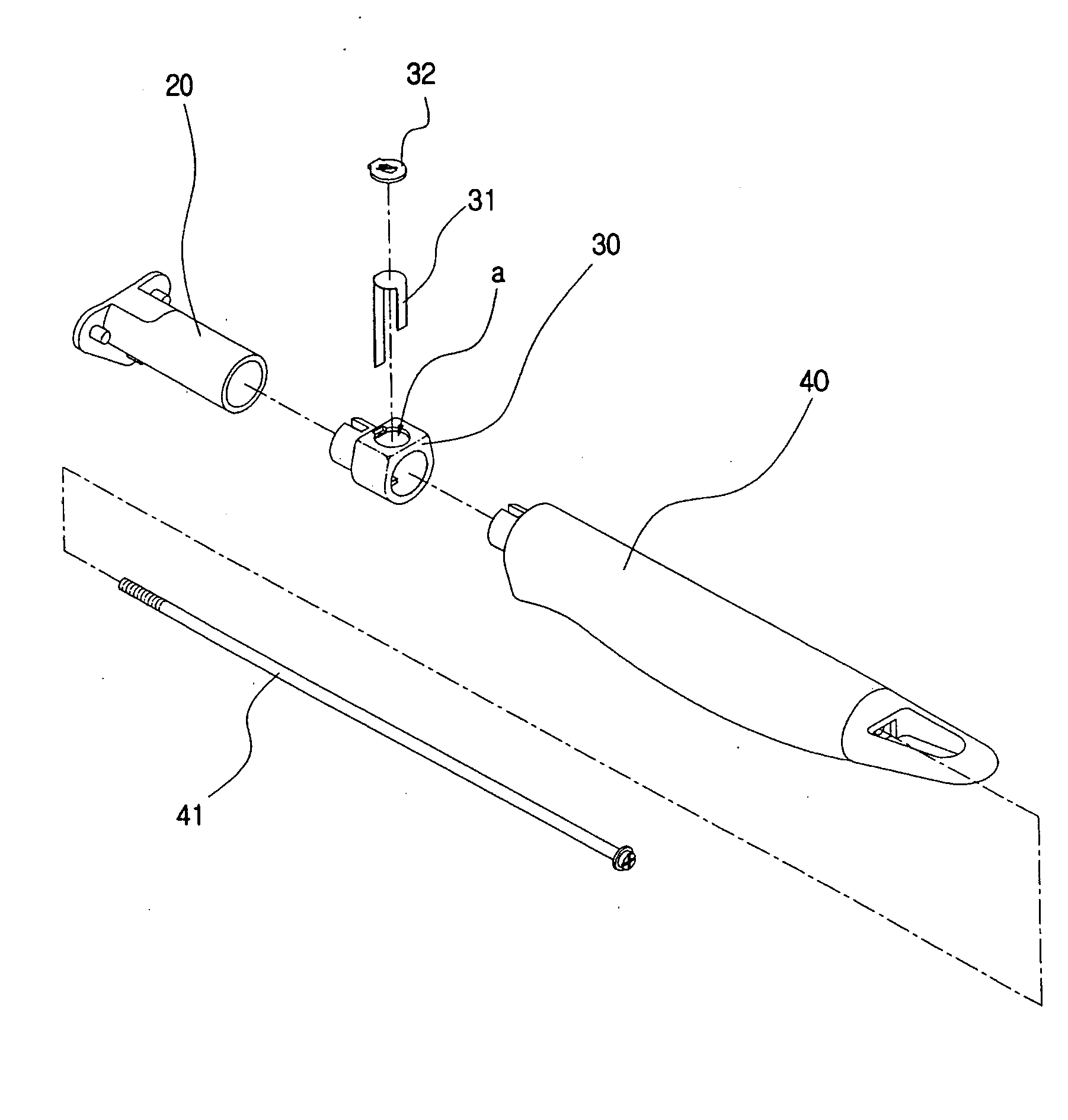
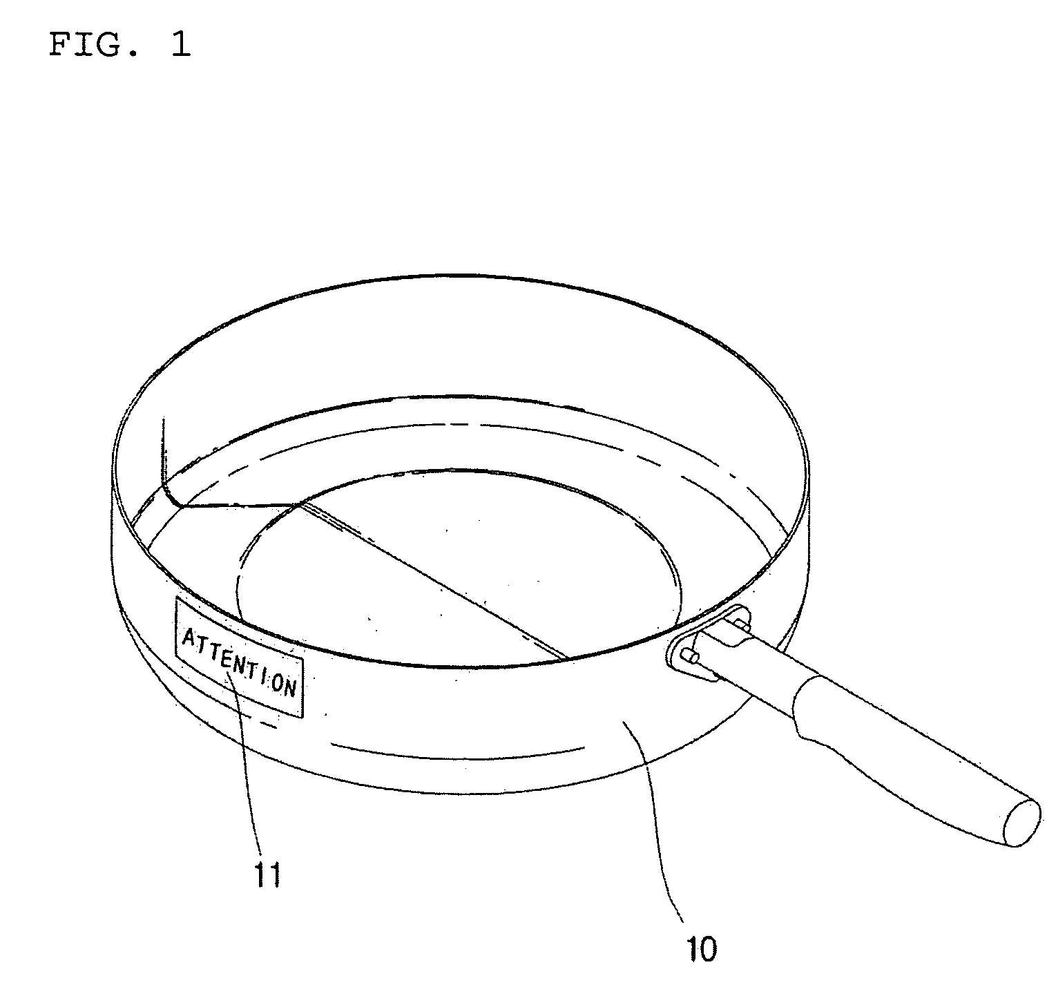
[0019]FIGS. 3 through 6 show a handle for cookware according to the present invention. As shown in the drawings, the handle for cookware according to the present invention is comprised of a mount part 20 joined to cookware 10 which opens upward, a connector part 30 disposed behind the mount part 20, and a grip part 40 coupled to the mount part 20 with the connector part 30 interposed therebetween. The mount part 20 is made of aluminum, and has a flange at its front end to enable the handle to be joined to a cookware 10 by rivets. The mount member 20 is provided at its front portion with an inner threaded hole and is provided at its rear portion with a larger insert hole. The connector part 30 is inserted at its front end into the rear insert hole of the mount part 20 and includes an insert hole at its rear end. The connector part 30 is provided at its upper surfac...


PUM


Abstract

A handle for cookware, which includes a temperature indicator to display temperature variations, is disclosed. The handle includes a mount part joined to a cookware and having a threaded hole, a grip part coupled to the mount part by a rod bolt that passes through the grip part and is screwed into the threaded hole of the mount part, and a connector part detachably coupled between the mount part and the grip part. The connector part includes a thermal conductor fitted in a fitting recess of the connector part and connected to the mount part. The thermal conductor has a thermochromic film or layer that changes in color at a predetermined temperature or higher.

Description

BACKGROUND OF THE INVENTION [0001] 1. Field of the Invention [0002] The present invention relates to a handle for cookware, and more particularly to a handle for cookware, which includes a connector part detachably coupled to a connecting end of the handle and having a temperature indicator to display temperature variations by change of color. [0003] 2. Description of the Prior Art [0004] Korean Utility Model Application No. 2003-10128, which is previously filed by the present inventor, discloses a cookware having a thermochromic film coated on an outer surface thereof, which changes in color at a predetermined temperature or higher. FIGS. 1 and 2 show the cookware disclosed in the above Application No. 2003-10128. As shown in FIGS. 1 and 2, the cookware 10 is provided with a thermochromic film 11 attached to its outer surface, which changes in color according to temperature variations. An outer surface of the film 11 is provided with a coating layer 12 of transparent heat-resisting...

Claims


Application Information

Patent Timeline
IPC IPC(8): A47J36/00A47J36/34A47J45/06A47J45/07
CPCA47J45/071A47J45/068A47J36/34
Inventor SON, JAE BONG
Owner DAE SUNG LIGHT METAL
Why Eureka
Try Eureka