Antenna

a technology of antennas and antennas, applied in the field of antennas, can solve the problems of inability to obtain a good multi-band antenna, radiation loss, and difficult efficient reception, and achieve the effect of excellent radio characteristics

Active Publication Date: 2005-06-23
CLARION CO LTD
View PDF3 Cites 11 Cited by
  • Summary
  • Abstract
  • Description
  • Claims
  • Application Information

AI Technical Summary

Benefits of technology

[0010] It is therefore an object of the present invention to provide a multi-band flat antenna, which shows excellent radio characteristics in each of multiple different frequency bands.
[0012] In the antenna according to the invention, for example by changing partially a thickness of the dielectric substrate having a flat back side, it is possible to form flat regions at different height levels on its front side, and it is possible to form the antenna patterns having lengths suited to respective frequency bands of the electric waves that each of the antenna patterns receives or transmits on these flat regions. And by setting the thicknesses of the respective flat regions of the dielectric substrate to thicknesses suited to the frequency bands of the electric waves that each of the antenna patterns provided on those flat regions receives or transmits, a flat antenna, which shows good radio characteristics with low radiation losses in those respective frequency bands, is formed.
[0013] Accordingly, with the invention, it is possible to form a flat antenna, which shows excellent radio characteristics in each of multiple different frequency bands.
[0015] A dielectric substrate having the regions like this can be easily made with a synthetic resin material.

Problems solved by technology

Now, in a case where this kind of idea for multi-band idea is applied to a patch antenna shown in FIGS. 5A and 5B of the drawings accompanying the present specification and a plurality of antenna patterns having different frequency bands are formed on the same plane region on a dielectric substrate in the form of a flat plate having a uniform thickness, it is not possible to obtain a good multi-band antenna showing characteristics corresponding to the required frequency bands.
However, in a case where the thickness B′ of the dielectric substrate 3 is greater than the length A′ of the antenna pattern 2B as shown in FIG. 5B, the electric field E readily deviates from the plate thickness direction, i.e. the direction toward the antenna pattern 2A, radiation losses arise, and efficient reception becomes difficult.

Method used


Image

  • Antenna
  • Antenna
  • Antenna

Examples


Embodiment Construction

[0026] The invention will now be described in detail with reference to a number of presently embodiments thereof.

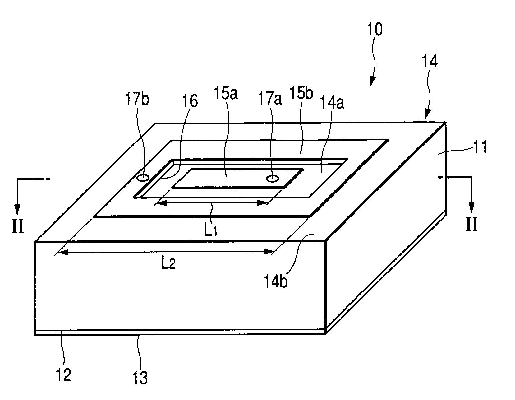
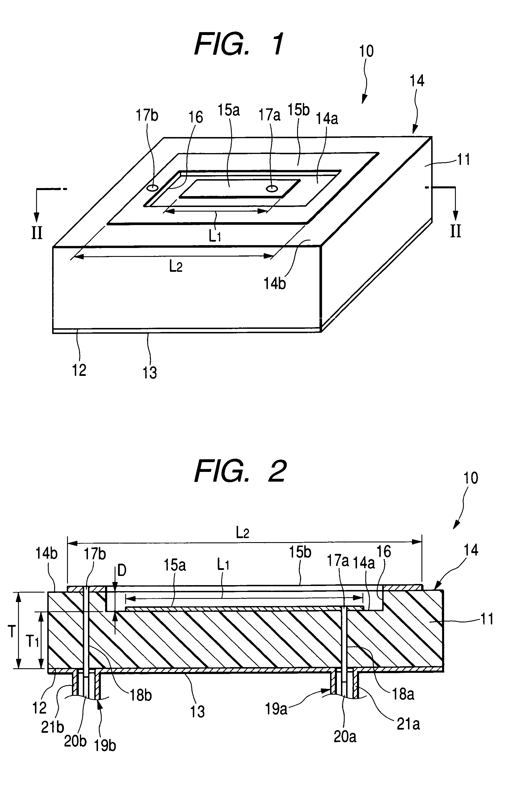
[0027]FIGS. 1 and 2 show a first preferred embodiment of the invention. As shown in FIG. 1, a patch antenna 10 according to the invention has a dielectric substrate 11, a grounding conductor 13 formed on a back side 12 of the dielectric substrate 11, and two antenna patterns 15 (15a and 15b) formed on a front side 14 of the dielectric substrate 11.

[0028] As shown in FIG. 2, the dielectric substrate 11 is made of a synthetic resin material in the shape of a plate having a substantially uniform plate thickness T, and the back side 12 is configured to be flat and is covered with the grounding conductor 13.

[0029] A rectangular recess 16 having a uniform depth D is entirely formed in the front side 14 of the dielectric substrate 11. A bottom region 14a of the recess 16 is parallel with the back side 12 of the dielectric substrate 11. The bottom region 14a of the recess 16 i...


PUM


Abstract

A multi-band flat antenna that shows excellent radio characteristics in each of multiple different frequency bands. In a patch antenna, a plurality of flat antenna patterns for different frequency bands are formed on a dielectric substrate. The dielectric substrate has different plate thicknesses in each of the regions where the flat antenna patterns are formed.

Description

BACKGROUND OF THE INVENTION [0001] 1. Field of the Invention [0002] This invention relates to a flat antenna, and particularly to a so-called multi-band antenna effective in a plurality of different frequency bands. [0003] 2. Description of the Related Art [0004] Antennas in related art include multi-band antennas that handle a UHF signal and an LF signal. (For example refer to JP-A-7-30316, Page 3, 4 and FIG. 2) [0005] As shown in FIG. 2 of JP-A-7-30316, an inner circular antenna element 7 and an outer annular antenna element 8 disposed on the same region as the inner circular antenna element surrounding the inner circular antenna element, and are provided on a circular plate 6 made of a dielectric material. Both of the antenna elements 7 and 8 are used for transmitting UHF signals, and the outer annular antenna element 8 is used for receiving LF signals. Accordingly, the transmission of UHF signals and reception of LF signals, which are in mutually different frequency bands, are p...

Claims


Application Information

Patent Timeline
Patent Type & Authority Applications(United States)
IPC IPC(8): H01Q1/38H01Q13/08H01Q5/10H01Q5/35H01Q5/40H01Q9/04
CPCH01Q9/0414H01Q5/40H01Q9/0464
Inventor UEDA, OSAMU
Owner CLARION CO LTD
Why Eureka
Try Eureka