
Apparatus and method for positioning mobile station

a mobile station and apparatus technology, applied in the direction of electrical apparatus, wireless communication, selection arrangements, etc., can solve the problems of inability to receive an sch from another bts, degrade the accuracy of the calculated value of the e-otd, and affect the accuracy of the calculation of the mobile station, so as to achieve the effect of accurate calculation of the location of mobile stations and efficient receiving of synchronization channels

Active Publication Date: 2005-06-23
ROVI GUIDES INC
View PDF7 Cites 50 Cited by
  • Summary
  • Abstract
  • Description
  • Claims
  • Application Information

AI Technical Summary

Benefits of technology

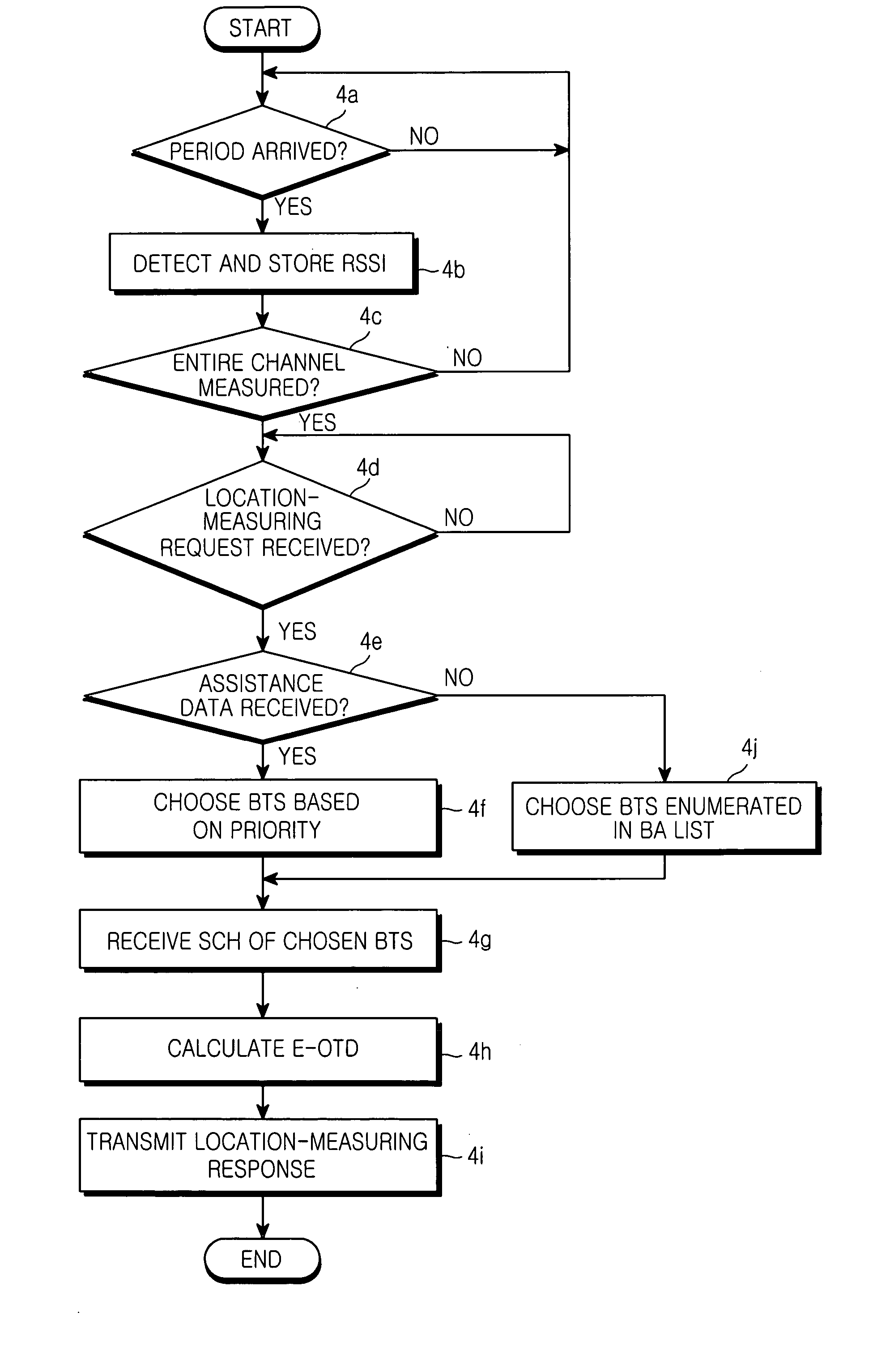
[0027] Accordingly, the present invention has been made to solve the above-mentioned problems occurring in the prior art, and an object of the present invention is to provide an apparatus and a method to accurately calculate the location of mobile stations, which uses assistance data, by receiving synchronization channels more efficiently.

Problems solved by technology

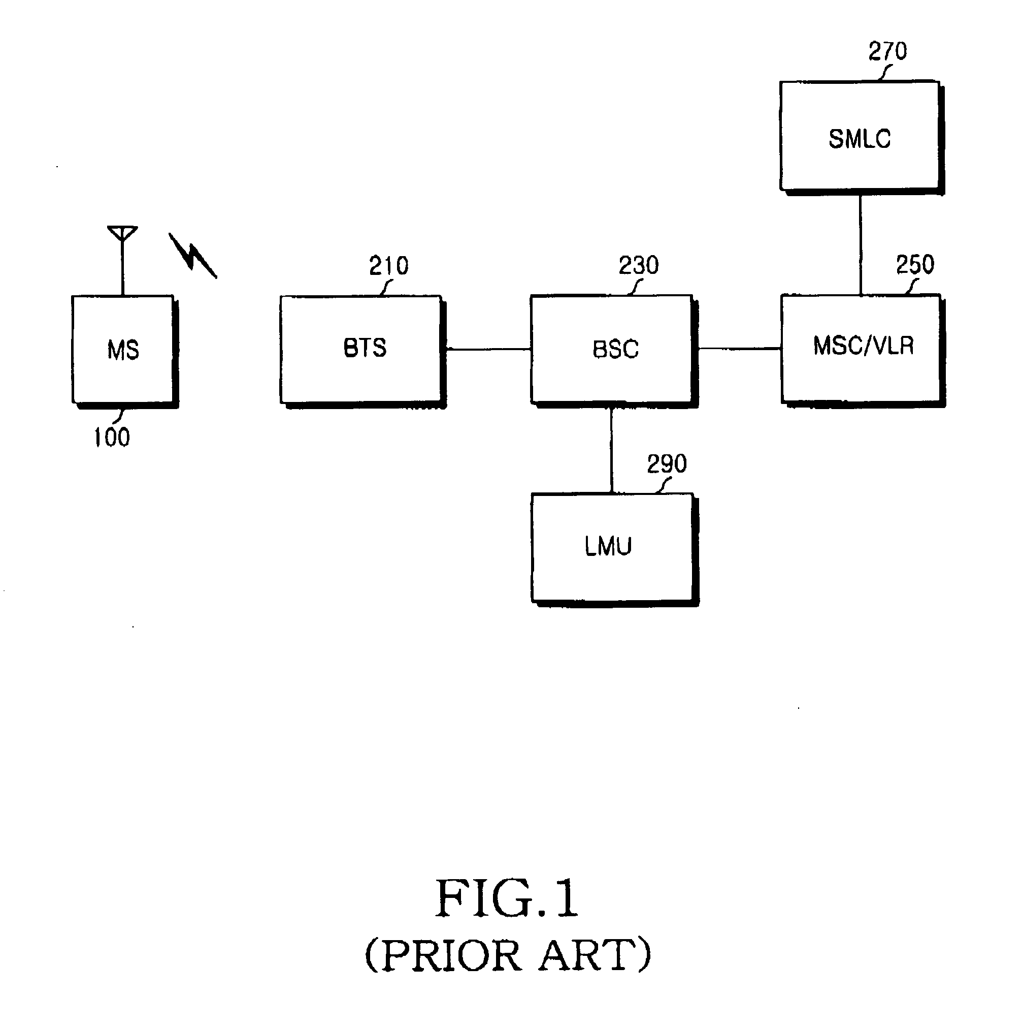
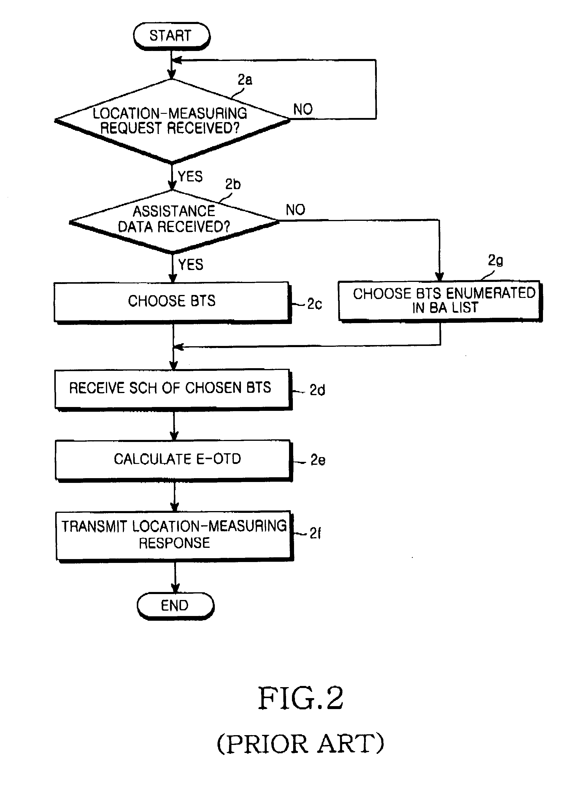
However, if locations of nearby BTSs, which are enumerated in the BA list, are difficult to calculate for geographical reasons, accuracy can deteriorate even when SCHs of the BTSs are received.
If the choice is inappropriate, the accuracy of the calculated value of the E-OTD may be degraded.
Under this assumption, when an MS fails to receive an SCH from a BTS due to weak signal intensity, it cannot receive an SCH from another BTS because the time has expired.
Furthermore, there is no method for obtaining a receipt gain for BTSs which are not defined in the BA list, although their BCH frequency numbers are defined in the assistance data.
This decreases the possibility of receiving SCHs and degrades the accuracy in calculating locations.

Method used


Image

  • Apparatus and method for positioning mobile station
  • Apparatus and method for positioning mobile station
  • Apparatus and method for positioning mobile station

Examples


Embodiment Construction

[0035] Hereinafter, preferred embodiments of the present invention will be described with reference to the accompanying drawings. In the following description of the present invention, particulars such as exemplary response time are given only to help the general understanding of the present invention and it will be obvious to those skilled in the art that the present invention can be realized without such particulars. A detailed description of known functions and configurations incorporated herein will be omitted when it may make the subject matter of the present invention unclear.

[0036]FIG. 3 is a diagram illustrating the construction of a mobile station adapted to measure its location using assistance data according to a preferred embodiment of the present invention.

[0037] In the drawing, particulars which are generally known in the art and correspond only to a mobile station's own function (for example, a voice coder or a voice recognition unit under an assumption that the mob...


PUM


Abstract

An apparatus and a method for calculating an enhanced observed time difference from a mobile station and transmitting the enhanced observed time difference to a servicing mobile location center for a location-based service are provided. The apparatus comprises means for receiving a location-measuring request and assistance data from the servicing mobile location center; means for choosing a base transceiver station, the synchronization channel of which is to be measured, based on response time detected from the location-measuring request and a predetermined priority; and means for calculating an enhanced observed time difference for the chosen base transceiver station and transmitting a location-measuring response, including the calculation result, to the servicing mobile location center. A first priority is assigned to an overlap between a channel list included in the assistance data and a list of a number of nearby cells and a second priority is assigned to a broadcast control channel allocation list except the channel list included in the assistance data and the list of nearby cells.

Description

PRIORITY [0001] This application claims priority to an application entitled “An Apparatus And A Method For Positioning A Mobile Station” filed with the Korean Intellectual Property Office on Dec. 17, 2003 and assigned Serial No. 2003-92461, the contents of which are incorporated herein by reference. BACKGROUND OF THE INVENTION [0002] 1. Field of the Invention [0003] The present invention relates to an apparatus and a method for positioning a mobile station in an LBS (location-based service) system, and more particularly to an apparatus and a method for calculating an E-OTD (enhanced observed time difference) and transmitting the E-OTD to a SMLC (serving mobile location center) using a mobile station. [0004] 2. Description of the Related Art [0005] Positioning technologies used in an LBS include a network-based positioning method, a handset-based positioning method, and a hybrid positioning method which alleviate the defects of the first two methods. [0006] The handset-based position...

Claims


Application Information

Patent Timeline
IPC IPC(8): H04B7/26H04W64/00
CPCH04W64/00
Inventor KANG, BYUNG-HAN
Owner ROVI GUIDES INC
Learn More