
Apparatus and method for transmitting and receiving a frame including control information in a broadcasting system

a broadcasting system and apparatus technology, applied in the field of broadcasting systems, can solve the problems of fatal error, inability of the receiver to directly or substantially gain the desired power reduction effect, and inability to achieve the intended power saving effect of the receiver, and achieve the effect of efficient transmission of control information

Active Publication Date: 2009-08-27
SAMSUNG ELECTRONICS CO LTD
View PDF12 Cites 61 Cited by
  • Summary
  • Abstract
  • Description
  • Claims
  • Application Information

AI Technical Summary

Benefits of technology

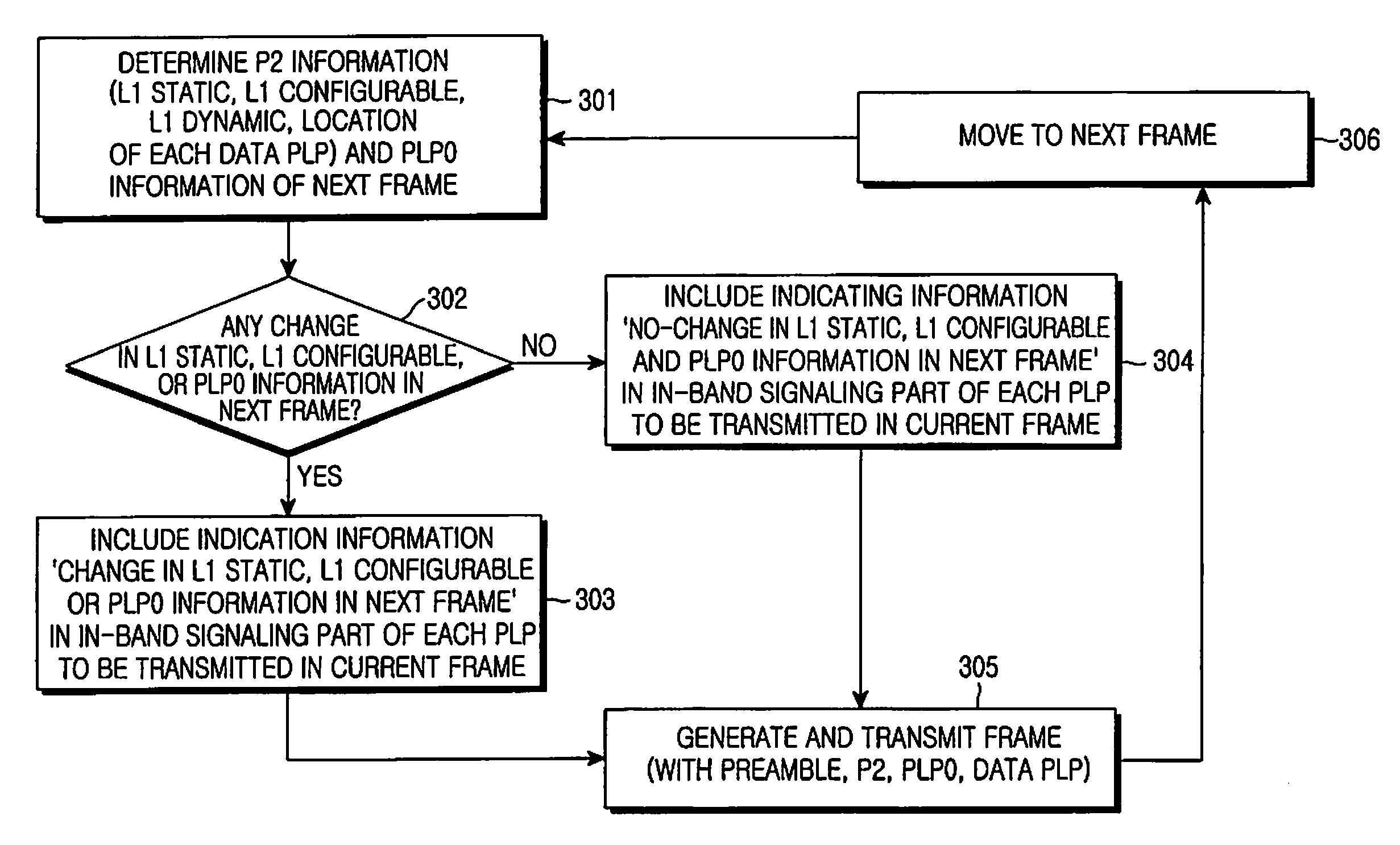
[0026]The present invention has been designed to address at least the problems and / or disadvantages and to provide at least the advantages described below. Accordingly, an aspect of an embodiment of the present invention is to provide an apparatus and method for efficiently transmitting control information for a broadcast service by applying an improved in-band signaling scheme in a broadcasting system.
[0031]Another aspect of an embodiment of the present invention is to provide an apparatus and method for efficiently receiving control information for a broadcast service to which an in-band signaling scheme is applied in a broadcasting system.
[0036]Another aspect of an embodiment of the present invention is to provide a reception apparatus and method for saving power of a receiver by transmitting and receiving control information related to a broadcast service in a frame using an improved in-band signaling scheme in a broadcasting system.

Problems solved by technology

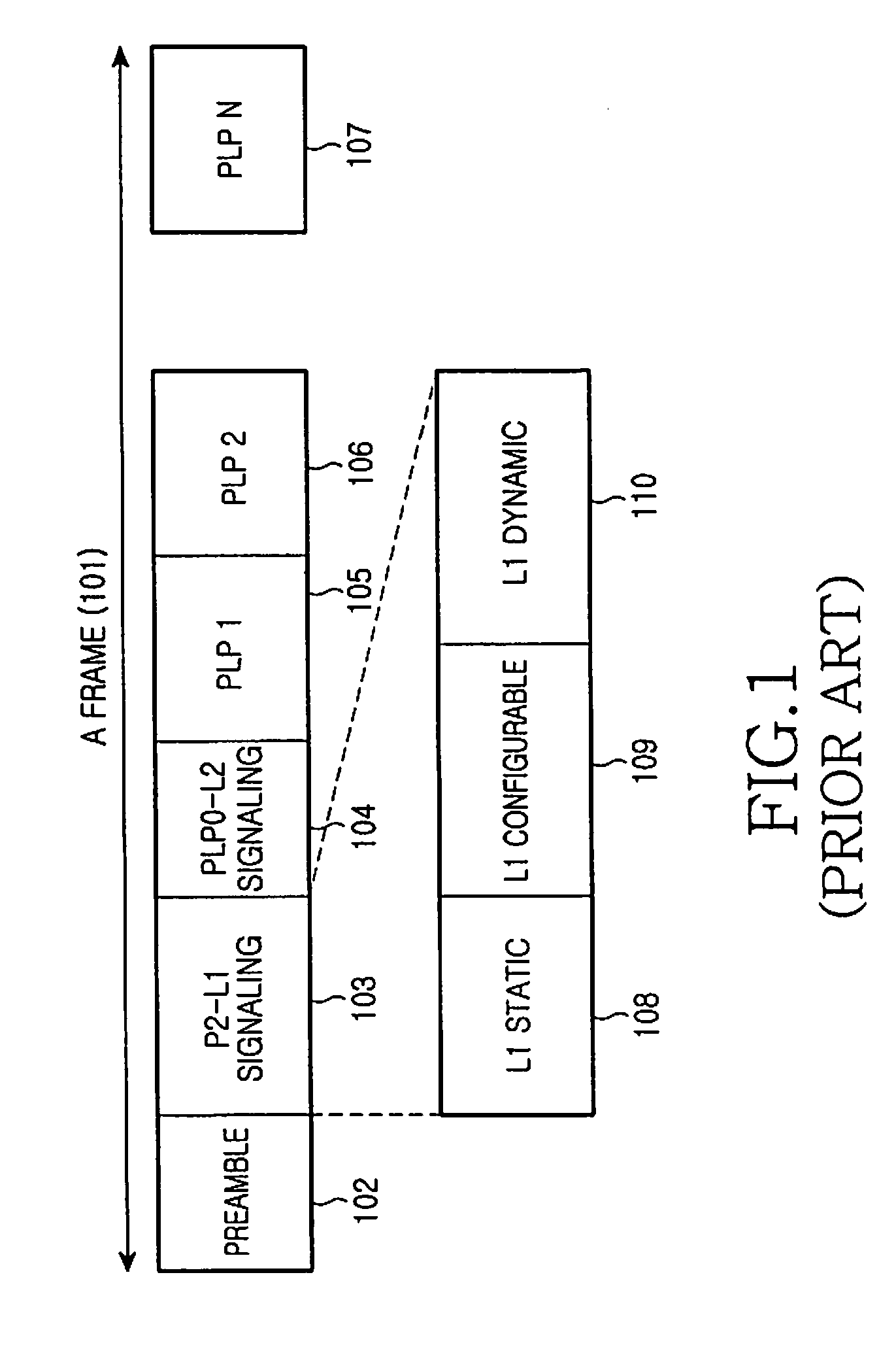
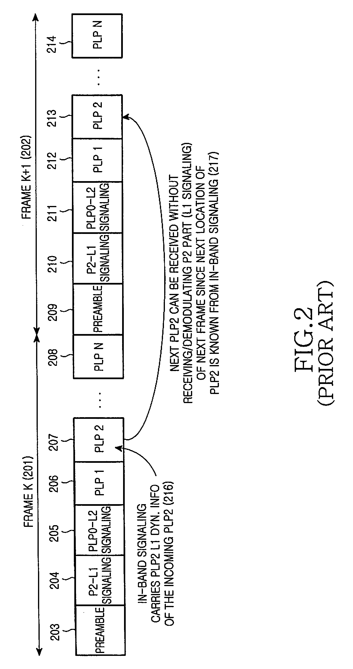
However, with regard to support for the actual broadcast service, the receiver using the in-band signaling scheme may actually fail to directly or substantially gain the desired power reduction effect.
As a result, the conventional in-band signaling scheme fails to result in the intended power savings for the receiver.
More specifically, even though information in the L2 signaling 211 transmitted through the PLP0 has changed, if the receiver fails to detect the change, a fatal error may occur when the receiver receives broadcast data later on.

Method used


Image

  • Apparatus and method for transmitting and receiving a frame including control information in a broadcasting system
  • Apparatus and method for transmitting and receiving a frame including control information in a broadcasting system
  • Apparatus and method for transmitting and receiving a frame including control information in a broadcasting system

Examples


Embodiment Construction

[0026]The present invention has been designed to address at least the problems and / or disadvantages and to provide at least the advantages described below. Accordingly, an aspect of an embodiment of the present invention is to provide an apparatus and method for efficiently transmitting control information for a broadcast service by applying an improved in-band signaling scheme in a broadcasting system.

[0027]Another aspect of an embodiment of the present invention is to provide an apparatus and method for generating a frame for a broadcast service by applying an improved in-band signaling scheme and transmitting the frame in a broadcasting system.

[0028]Another aspect of an embodiment of the present invention is to provide an apparatus and method for including, in the current frame, indication information for indicating a change / no-change in control information included in the next frame, and transmitting the frame in a broadcasting system.

[0029]Another aspect of an embodiment of the...


PUM


Abstract

Apparatus and method for transmitting and receiving a frame including control information in a broadcasting system. A frame for a broadcast service is generated using an in-band signaling scheme, and includes location information of control information in a next frame and indication information indicating a change / no-change in the control information in the next frame. The new frame structure minimizes power consumption of a receiver supporting the broadcast service.

Description

PRIORITY[0001]This application claims priority under 35 U.S.C. §119(a) to a Korean Patent Application filed in the Korean Intellectual Property Office on Feb. 21, 2008 and assigned Serial No. 10-2008-0015825, a Korean Patent Application filed in the Korean Intellectual Property Office on Mar. 13, 2008 and assigned Serial No. 10-2008-0023568, and a Korean Patent Application filed in the Korean Intellectual Property Office on Mar. 14, 2008 and assigned Serial No. 10-2008-0024086, the disclosures of all of which are incorporated herein by reference.BACKGROUND OF THE INVENTION[0002]1. Field of the Invention[0003]The present invention relates generally to a broadcasting system, and in particular, to an apparatus and method for transmitting and receiving a frame including control information.[0004]2. Description of the Related Art[0005]Today, with the development of communication and broadcasting technologies, attempts are being made to find new ways to provide broadcast services in broad...

Claims


Application Information

Patent Timeline
Patent Type & Authority Applications(United States)
IPC IPC(8): H04L12/56H04J3/24
CPCH04H20/42H04H20/93H04H60/13H04W4/06H04L49/1546H04L12/56H04H60/25Y02D30/70
Inventor KWON, HWAN-JOONLEE, HAK-JULIM, YEON-JUJEONG, HONG-SILKIM, JAE-YOELYUN, SUNG-RYULMYUNG, SEHO
Owner SAMSUNG ELECTRONICS CO LTD
Learn More