Method for train positioning

a technology for positioning trains and trains, applied in distance measurement, navigation instruments, instruments, etc., can solve the problems of increasing maintenance work, re-installation of balises, and enormous costs associated with data re-writing and other problems

Inactive Publication Date: 2005-06-23
HITACHI LTD
View PDF17 Cites 35 Cited by
  • Summary
  • Abstract
  • Description
  • Claims
  • Application Information

AI Technical Summary

Benefits of technology

[0010] An object of the present invention is to provide a method for train positioning requiring no balises for train position detection by which each train can detect its own position as a movement di

Problems solved by technology

However, if it is intended to install many balises to enable each train to detect its own position, the labor of the maintenance work is inevitably increased due to the installation thereof and the balises are generally installe

Method used


Image

  • Method for train positioning
  • Method for train positioning
  • Method for train positioning

Examples


Embodiment Construction

[0020] The embodiment of the present invention will be explained below with reference to FIGS. 1 to 6.

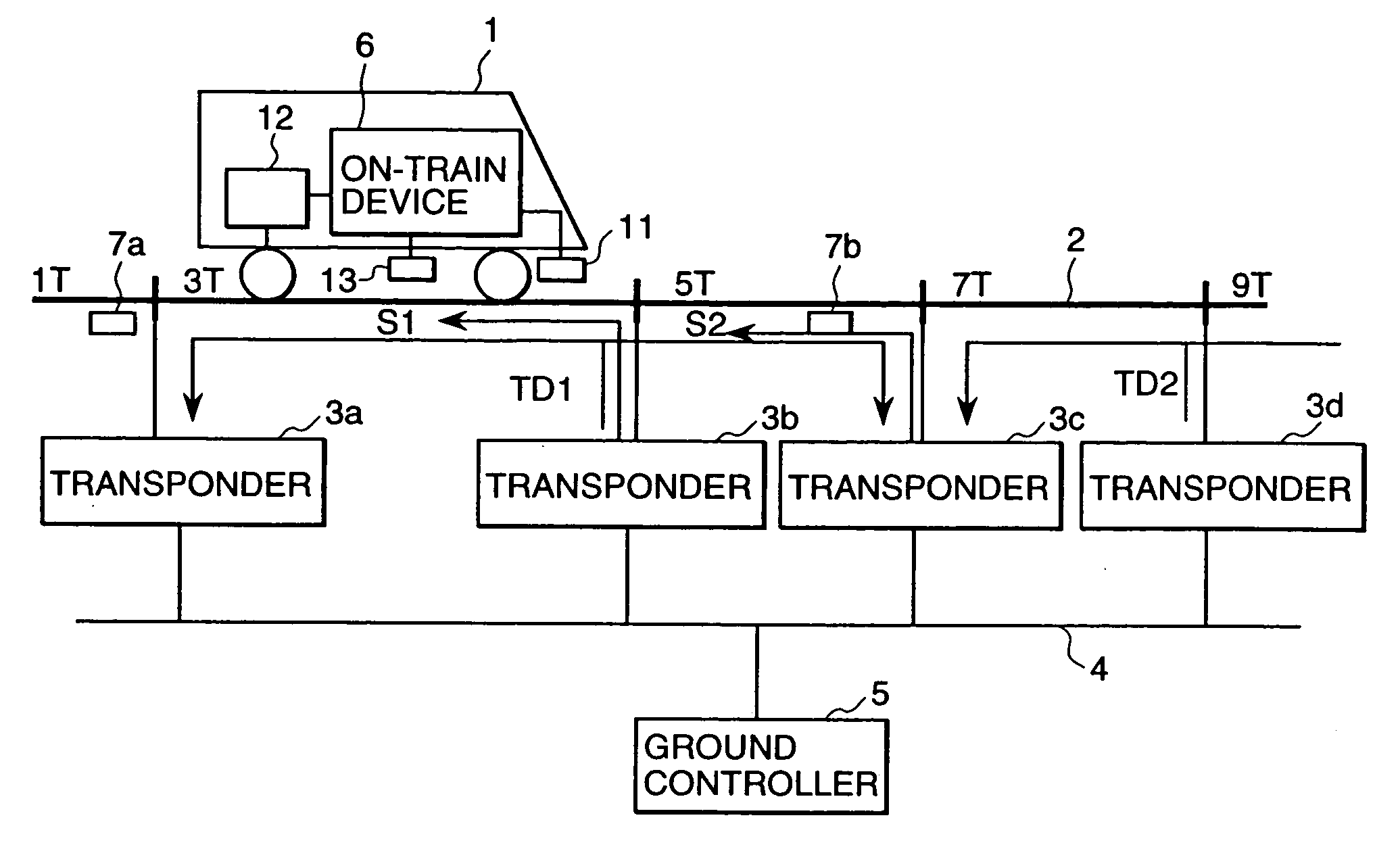
[0021] Firstly, the automatic train control system relating to the present invention will be explained. The system configuration which is an example thereof is shown in FIG. 1. As shown in the drawing, on a train 1, an on-train device 6, a receiver 11, a wayside coil 13, and a speed generator 12 are loaded as on-train equipment and among them, the on-train device 6, on the basis of pulse output from the speed generator 12, detects the preceding speeds of the train 1 and the preceding travel distance of the train 1 as an integrated value thereof. Further, the receiver 11 receives train control signals S1 and S2 and train detection signals TD1 and TD2 flowing on the track circuits and then transfers them to the on-train device 6. Furthermore, the wayside coil 13, when the train 1 passes the balises, receives information from the balises and transfers it to the on-train device 6.

[002...


PUM


Abstract

In the state that a train moves from a track circuit 3T toward a track circuit 5T, and a train detection signal TD1 is supplied from the boundary between the track circuits 3T and 5T to the track circuits 3T and 5T, and the train detection signal TD1 is received by the train, if the signal intensity is suddenly reduced greatly immediately after the axle of the train passes the boundary between the track circuits 3T and 5T, it can be decided that the train passes the boundary between the track circuits 3T and 5T. Therefore, if absolute position information of the track circuit 5T is preserved beforehand in the train, the movement distance calculated from pulse output of a speed generator is corrected (replaced) in the absolute position information of the track circuit 5T, and hereafter is updated by the pulse output, thus the position of the own train can be easily detected as a movement distance.

Description

CROSS-REFERENCE TO A RELATED APPLICATION [0001] This application claims the benefit of the filing date of Japanese Patent Application, Serial No. 2003-423179, Filed on Dec. 19, 2003. BACKGROUND OF THE INVENTION [0002] 1. Field of the Invention [0003] The present invention relates to a method for train positioning of an automatic train control system composed of ground equipment including transponders and track circuits and on-train equipment including an on-train device and a wayside coil loaded on a train and more particularly to a method for train positioning for detecting the position of each of trains as a movement distance by on-train equipment loaded on the train without using balises. [0004] 2. Description of Prior Art [0005] The basic object of a signaling safety system of a railroad is to exclusively control incoming into a block section for each train to prevent rear-end collision and derailment of the train. As a conventional signaling safety system, in addition to an int...

Claims


Application Information

Patent Timeline
IPC IPC(8): B61L3/08B61L1/18B61L3/12B61L25/00B61L25/02G01C22/00G06F17/00H04Q9/00
CPCB61L1/18B61L25/026B61L25/025B61L3/121B61L3/08
Inventor WATANABE, DAIOGUMA, KENJIAMIYA, NORIHARU
Owner HITACHI LTD
Why Eureka
Try Eureka