
Equipment rack load modulation system and method

a rack load and rack load technology, applied in the direction of instruments, power supply for data processing, cooling/ventilation/heating modification, etc., can solve the problems of increasing complexity and difficulty of efficient rack equipment loading, raising many challenging operational issues, and difficult to optimize rack equipment loading and associated performance parameters of centralized resource operations

Inactive Publication Date: 2005-06-23
HEWLETT PACKARD DEV CO LP
View PDF24 Cites 62 Cited by
  • Summary
  • Abstract
  • Description
  • Claims
  • Application Information

AI Technical Summary

Benefits of technology

The patent describes a system and method for managing the heat and power usage of equipment in a rack. It determines the overall thermal and power needs of the rack and allocates it to the different equipment based on its load. The equipment then operates within this allocation. The technical effect is to optimize the use of resources and reduce energy consumption in data centers.

Problems solved by technology

While leveraged utilization of centralized resources is usually advantageous, optimally balancing rack loading and associated performance parameters of centralized resource operations is usually very difficult.
Balancing the rack loading from minimal to maximum capacity raises many challenging operational issues.
The differences in rack equipment typically included in centralized computing resource racks usually increases the complexity and difficulty of efficient rack equipment loading.
Loading a rack with equipment that operates within the overall rack power and thermal budget is often problematic.
For example, the power consumption and thermal profile of typical rack equipment (e.g., server computers) is such that more rack equipment can be physically located or “housed” within a rack than can be cooled and / or power continuously provided for.
In addition, conventional tendencies for operating rack equipment at fixed predetermined performance levels does not promote efficient use of a power consumption and heat dissipation budget.
Traditional attempts at maintaining rack power and thermal budgets by limiting the amount of equipment loaded in a rack usually results in more racks occupying precious floor space.
Traditional attempts also sometimes limit rack equipment loading to rack equipment with relatively low power operating characteristics which can result in significant performance limitations and / or the need for additional equipment to make up for the performance limitations.

Method used


Image

  • Equipment rack load modulation system and method
  • Equipment rack load modulation system and method
  • Equipment rack load modulation system and method

Examples


Embodiment Construction

[0011] Reference will now be made in detail to the preferred embodiments of the invention, examples of which are illustrated in the accompanying drawings. While the invention will be described in conjunction with the preferred embodiments, it will be understood that they are not intended to limit the invention to these embodiments. On the contrary, the invention is intended to cover alternatives, modifications and equivalents, which may be included within the spirit and scope of the invention as defined by the appended claims. Furthermore, in the following detailed description of the present invention, numerous specific details are set forth in order to provide a thorough understanding of the present invention. However, it is understood the present invention may be practiced without these specific details. In other instances, some readily understood methods, procedures, components, and circuits have not been described in detail as not to unnecessarily obscure aspects of the current ...


PUM


Abstract

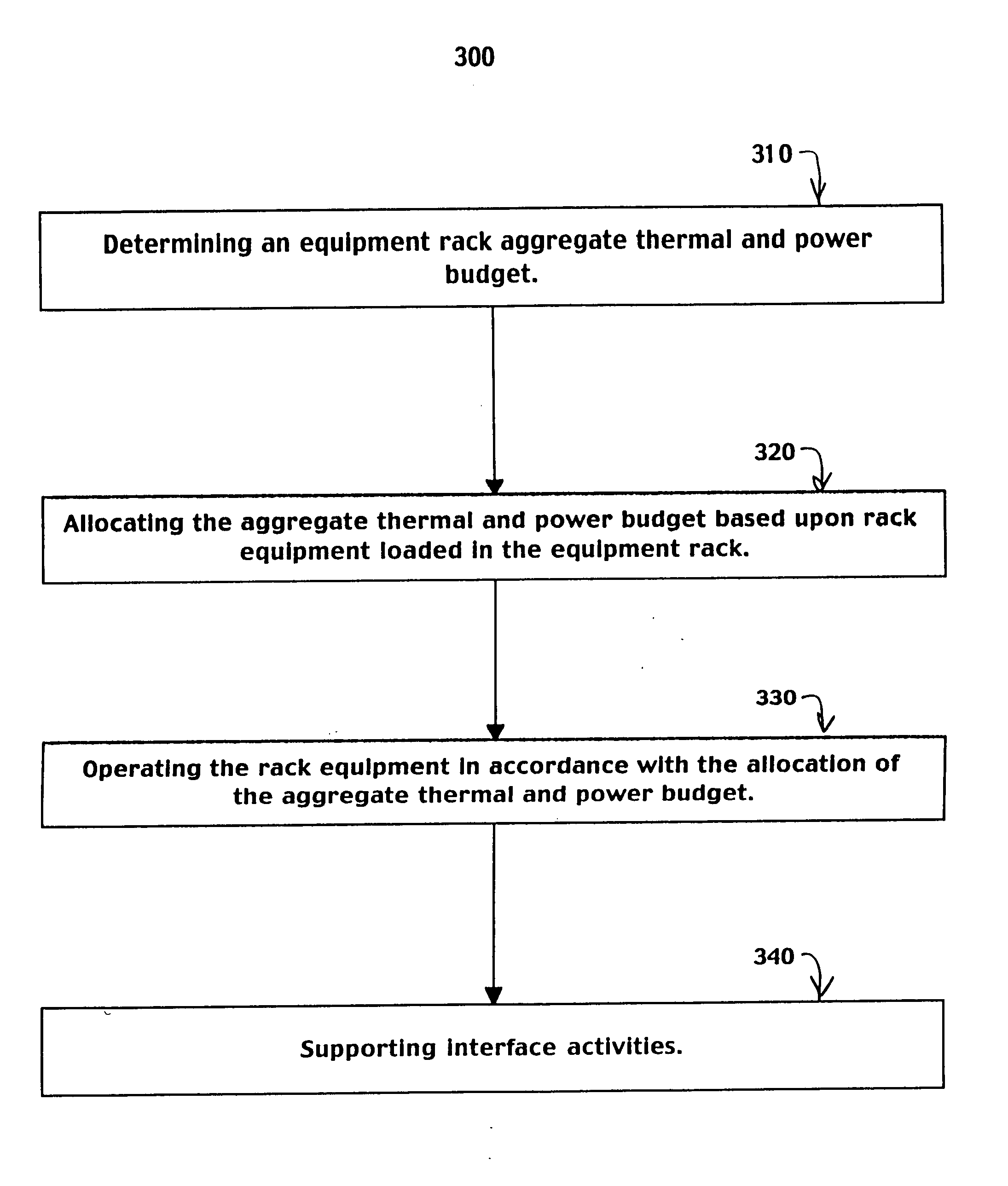
An equipment rack load modulation system and method are presented. An equipment rack aggregate thermal and power budget is determined. The aggregate thermal and power budget is allocated based upon rack equipment loaded in an equipment rack. The rack equipment is then operated in accordance with the allocation of the aggregate thermal and power budget.

Description

FIELD OF THE INVENTION [0001] The present invention relates to rack equipment management. BACKGROUND OF THE INVENTION [0002] Electronic systems and circuits have made a significant contribution towards the advancement of modern society and are utilized in a number of applications to achieve advantageous results. Numerous electronic technologies such as digital computers, calculators, audio devices, video equipment, and telephone systems have facilitated increased productivity and reduced costs in analyzing and communicating data, ideas and trends in most areas of business, science, education and entertainment. Frequently, electronic systems designed to provide these advantageous results are realized through the leveraged utilization of centralized resources by distributed network nodes. While leveraged utilization of centralized resources is usually advantageous, optimally balancing rack loading and associated performance parameters of centralized resource operations is usually very...

Claims


Application Information

Patent Timeline
Patent Type & Authority Applications(United States)
IPC IPC(8): G06F1/00G06F1/20G06F1/26G06F1/30G06F1/32H05K7/20
CPCG06F1/206G06F1/3203G06F1/26
Inventor BARR, ANDREW HARVEYBRESNIKER, KIRK MICHAELESPINOZA-IBARRA, RICARDO
Owner HEWLETT PACKARD DEV CO LP
Learn More