Apparatus providing plural wireless transceivers within a desired power budget and associated method

a technology of wireless transceivers and accessories, applied in the field of wireless communication, can solve the problems of affecting the performance of the wireless device, and affecting and reducing the overall performance of the wireless devi

Active Publication Date: 2010-08-26
ROLLING WIRELESS S.À R L
View PDF29 Cites 52 Cited by
  • Summary
  • Abstract
  • Description
  • Claims
  • Application Information

AI Technical Summary

Benefits of technology

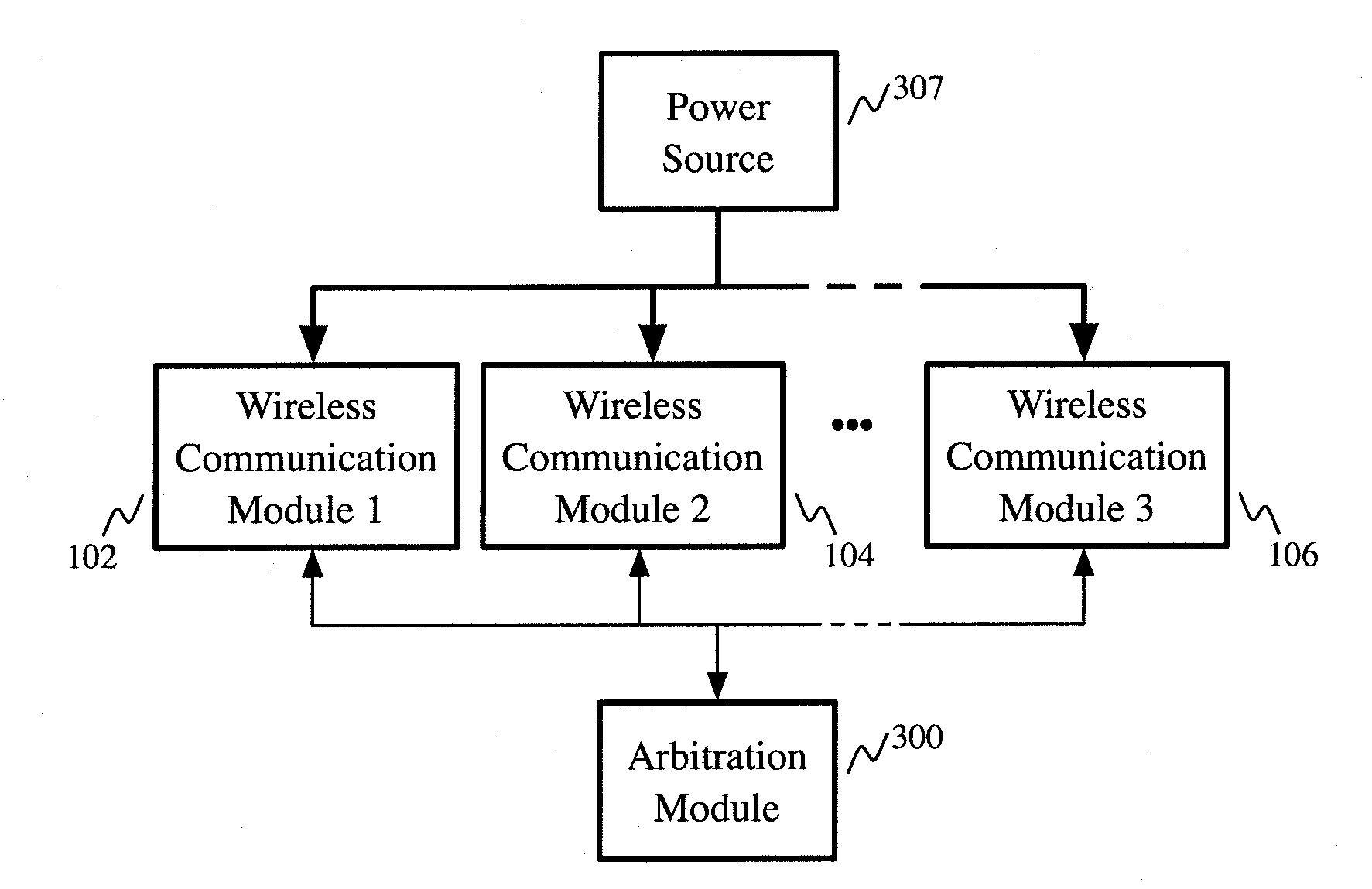
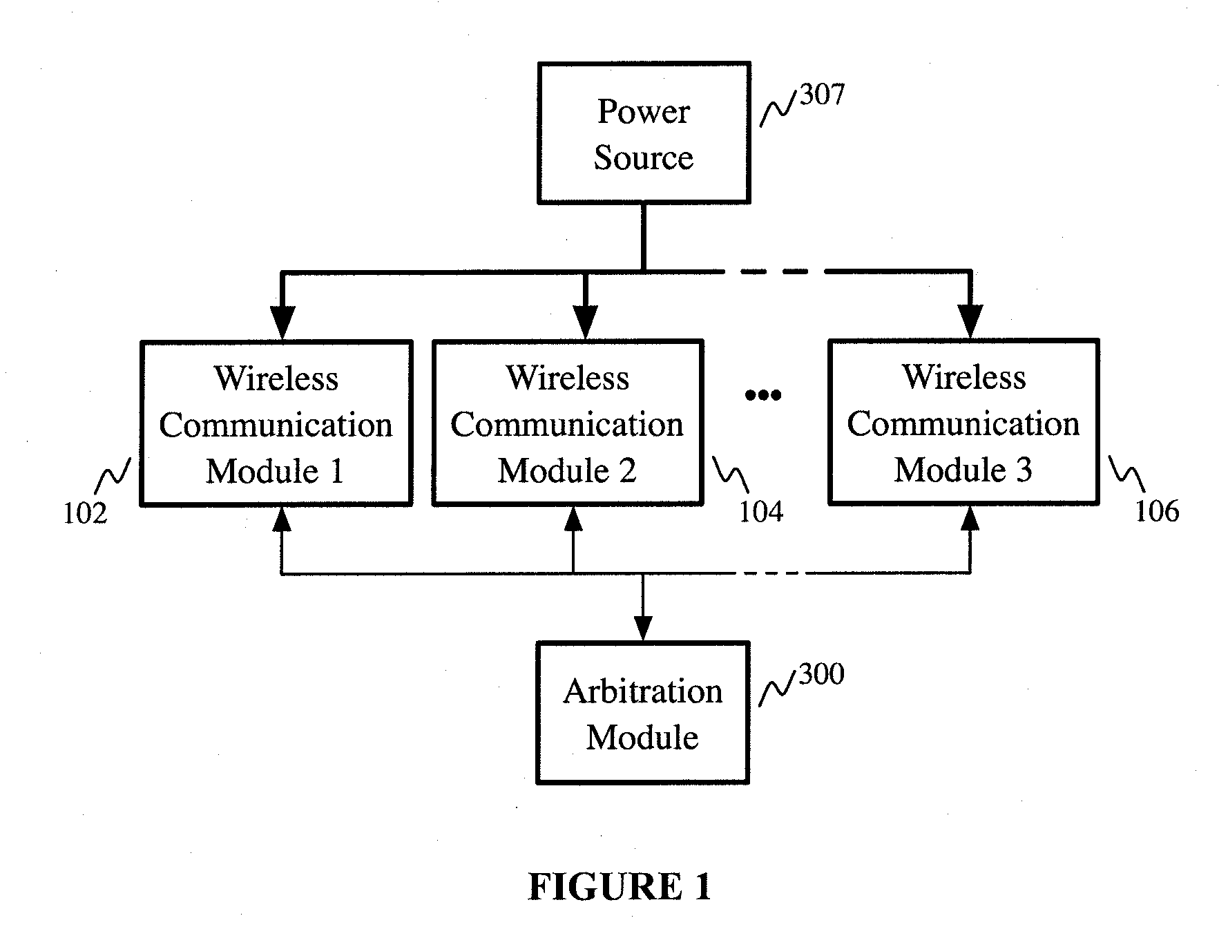
[0009]An object of the present invention is to provide an apparatus providing plural wireless transceivers within a desired power budget and associated methods. In accordance with an aspect of the present invention, there is provided a wireless communication apparatus comprising: a plurality of wireless communication modules, each of the plurality of wireless communication modules having a lower-power state and a higher-power state; a power source operatively coupled to the plurality of wireless communication modules for delivering power thereto; and an arbitration module operatively coupled to the plurality of wireless communication modules, the arbitration module configured to control which of the plurality of wireless communication modules are in the higher-power state, thereby controlling total power delivered by the power source to the plurality of wireless communication modules.
[0010]In accordance with another aspect of the present invention, there is provided a method for providing a plurality of wireless communication capabilities within a desired power budget, the method comprising: providing a plurality of wireless communication modules associated with the plurality of wireless communication capabilities, each of the plurality of wireless communication modules having at least a lower-power state and a higher-power state, each of the plurality of wireless communication modules operatively coupled to a power source to receive power therefrom; and controlling which of the plurality of wireless communication modules are in the higher-power state, thereby controlling total power delivered by the power source to the plurality of, wireless communication modules.
[0011]In accordance with another aspect of the present invention, there is provided a computer program product comprising a computer readable medium having recorded thereon statements and instructions for execution by a computer to carry out a method for operating a plurality of wireless communication capabilities, each of the plurality of wireless communication modules operatively coupled to a power source to receive power therefrom, the method comprising: controlling which of the plurality of wireless communication modules are in a higher-power state and controlling which of the plurality of wireless communication modules are in a lower-power state, thereby controlling total power delivered by the power source to the plurality of wireless communication modules.

Problems solved by technology

Challenges for creating such multi-mode devices include cost, size, performance, and power constraints.
However, such generic, reconfigurable components typically behave poorly with respect to indicators such as performance and cost.
In addition, reconfiguration operations may require additional time, further reducing overall performance of the wireless device.
However, incorporating plural single-mode communication modules into a common wireless device may cause operating problems when there are power limitations.
For example, operation of more than one wireless communication module at a time typically requires increased power, which may be above rated power limitations, thereby causing functional problems and / or device damage.
Such limitations are apparent, for example in wireless adapters having a universal serial bus (USB™) interface, where simultaneous operation of plural single-mode wireless communication modules may result in a current draw to the wireless adapter greater than the maximum rated current specified for the associated USB™ bus.

Method used


Image

  • Apparatus providing plural wireless transceivers within a desired power budget and associated method
  • Apparatus providing plural wireless transceivers within a desired power budget and associated method
  • Apparatus providing plural wireless transceivers within a desired power budget and associated method

Examples


example 1

[0076]Referring to FIG. 3, embodiments of the invention includes a wireless communication apparatus 105 coupled through a connector 110 to a host computer 100, which may be a special or general-purpose computer. The connector 110, such as a USB™ connector, has a data path 120 through which data can be transferred via electrical contact or via optical transmission or via magnetic induction or via capacitive coupling or the like. Said connector 110 also has a power path 305 through which power for the wireless communication apparatus 105 is transferred from the host processor 100, via electrical contact or via magnetic induction, to a power distribution system 107, which supplies power to components of the wireless communication apparatus 105. In this embodiment, the power source resides on the host processor 100.

[0077]Continuing with respect to FIG. 3, a first wireless communication module may comprise a baseband processor 130, up / down converter 140, power amplifier 150, antenna swit...

example 2

[0082]FIG. 4 illustrates a representation of the arbitration module 303 according to an embodiment of the present invention. The arbitration module 303 comprises digital logic that provides fixed pre-emptive prioritization of one wireless communication module over another. A logical level ‘1’ at input 163 or 233 indicates a request by the first or second wireless communication module, respectively, to enable that wireless communication module to enter a higher-power state, for example by enabling the power amplifier thereof. A logical level ‘1’ at output 313 or 323 indicates that the first or second wireless communication module is enabled to enter the higher-power state. As illustrated in FIG. 4, the first wireless communication module's request signal connection 163, if set to logical level ‘1’, disables the second wireless communication module's enable connection 323 by forcing it to logical level ‘0’. Thus, the first wireless communication module has pre-emptive priority over th...

example 3

[0083]FIG. 5 illustrates representation of another arbitration module 304 according to an embodiment of the present invention. The arbitration module 304 comprises digital logic that allows pre-emptive prioritization rules for wireless communication modules to be controlled by a prioritization configuration input 400. Said prioritization configuration input 400, when set to logical level ‘0’, results in the first wireless communication module having priority. In this case, the arbitration module operates similarly to that of Example 2. That is, a logical level ‘1’ at input 164 or 234 indicates a request by the first or second wireless communication module, respectively, to enable that wireless communication module to enter a higher-power state, for example by enabling the power amplifier thereof. A logical level ‘1’ at output 314 or 324 indicates that the first or second wireless communication module is enabled to enter the higher-power state. As illustrated in FIG. 4, the first wir...


PUM


Abstract

The present invention provides an apparatus providing plural wireless transceivers within a desired power budget and associated methods. A plurality of wireless communication modules, each having a lower-power state and a higher-power state are provided, drawing power from a common source. Arbitration is performed to control which of the plurality of wireless communication modules are in the higher-power state, thereby controlling total power delivered by the power source to the plurality of wireless communication modules.

Description

CROSS REFERENCE TO RELATED APPLICATIONS[0001]The present application claims priority under 35 U.S.C. §119 to U.S. Provisional Application Ser. No. 61 / 154,677, filed Feb. 23, 2009, entitled “APPARATUS PROVIDING PLURAL WIRELESS TRANSCEIVERS WITHIN A DESIRED POWER BUDGET AND ASSOCIATED METHOD” the disclosure of which is incorporated herein by reference.FIELD OF THE INVENTION[0002]The present invention pertains in general to wireless communications and in particular to an apparatus providing plural wireless transceiver capabilities within a desired power budget, and associated methods.BACKGROUND[0003]As the field of wireless communications develops, various wireless communication standards or protocols continue to be deployed. At a given location, it is becoming increasingly likely that one or more wireless networks are available for use, accessible via one of a variety of communication protocols. For example, Wi-Fi, Wi-MAX, CDMA, GSM, UMTS, and other communication protocols are current...

Claims


Application Information

Patent Timeline
Patent Type & Authority Applications(United States)
IPC IPC(8): H04B1/38
CPCH04W52/0264Y02B60/50H04W52/0274Y02D30/70H04W88/06H04W52/02
Inventor THOMAS, JOHN W.KAVANAUGH, RICHARD THOMASTHEOBALD, DAVID EUGENEKIELSZNIA, JEAN PHILIPPEVADATHAVOOR, BHASKAR S.VOS, GUSTAV GERALDCOATES LLOYD, KEVIN RUSSELL
Owner ROLLING WIRELESS S.À R L
Why Eureka
Try Eureka