Image sensing apparatus and power managing method

Inactive Publication Date: 2005-03-03
CANON KK
View PDF8 Cites 40 Cited by
  • Summary
  • Abstract
  • Description
  • Claims
  • Application Information

AI Technical Summary

Problems solved by technology

However, a conventional image sensing apparatus (such as a digital video camera or digital camera) consumes a large amount of power and cannot operate solely on power supplied from a USB interface.
In other words, there is not a

Method used


Image

  • Image sensing apparatus and power managing method
  • Image sensing apparatus and power managing method
  • Image sensing apparatus and power managing method

Examples


Example

[0021] [First Embodiment]

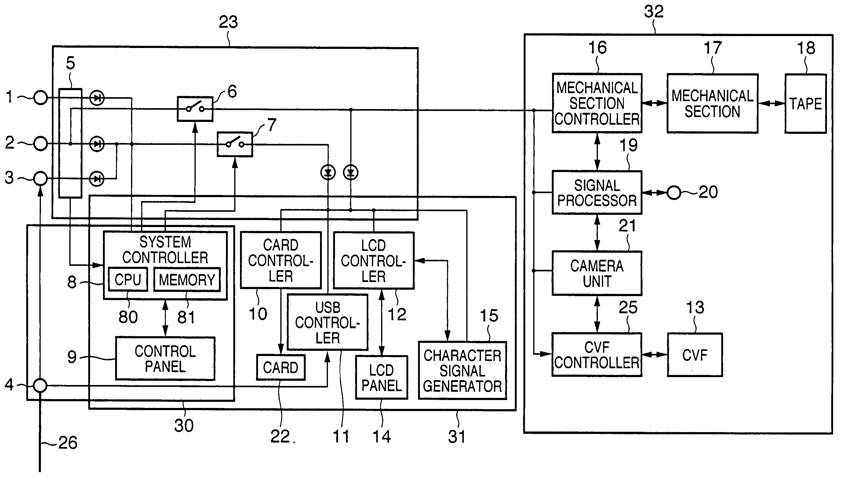
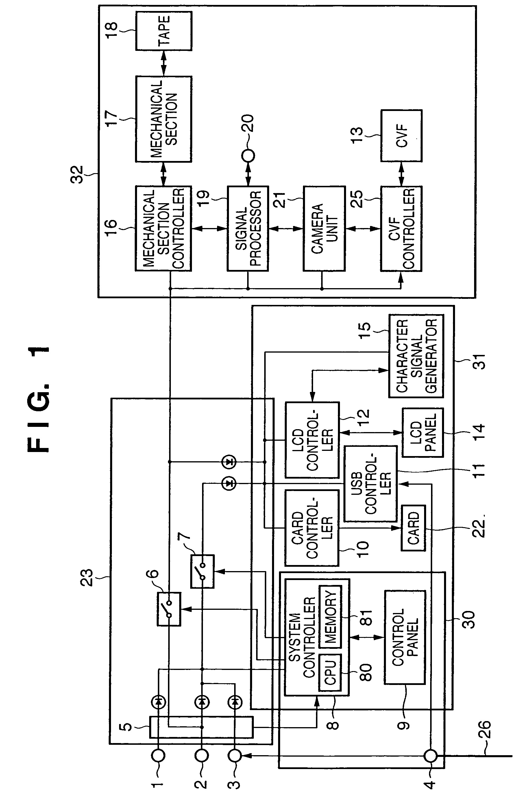
[0022]FIG. 1 is a block diagram illustrating the structure of a digital video camera 200 according to a first embodiment of the present invention.

[0023] As shown in FIG. 1, the digital video camera 200 has an input terminal 1 to which power is supplied from a back-up power source. The power applied to the terminal 1 is supplied to a system controller 8 at all times. An input terminal 2 receives power supplied from a main power source (an AC power source or a battery), and an input terminal 3 receives power (also referred to as “bus power”) supplied from a USB interface 4. The latter is an interface compliant with the above-mentioned USB 1.1 and USB 2.0 standards or standards similar thereto and has a connector for D+ and D− lines, a VBUS line and a GND line. As stipulated by the USB standards, the D+ and D− lines are lines for data transfer, and the VBUS and GND lines are lines for supplying power.

[0024] A power-source detector 5 has a function for detecti...

Example

[0048] [Second Embodiment]

[0049]FIG. 6 is a block diagram illustrating the structure of a digital video camera 200 according to a second embodiment of the present invention. Components in FIG. 7 identical with those in FIG. 1 are designated by like reference characters and need not be described again.

[0050] In FIG. 6, the power-source detector 5 has a function for detecting whether power being supplied to the terminal 2 from the main power source is sufficient or not, and a function for detecting whether power being supplied to the terminal 3 from the USB interface 4 is sufficient or not. When closed, the changeover switch 7 supplies bus power from the terminal 3 to the card controller 10 and USB controller 11. An LED 61 lights in order to indicate to the user the fact that the digital video camera 200 is running solely on bus power. A CVF & LCD controller 63 outputs the signal reproduced by the card controller 10, the reproduced signal on tape 18 from the mechanical section contro...


PUM


Abstract

If supply of power from a main power source is insufficient but power being supplied from a communication interface (such as a USB interface) is sufficient, an image sensing apparatus (such as a digital video camera or digital camera) supplies power from the communication interface to a limited number of components. As a result, the image sensing apparatus is capable of functioning as a bus-powered device.

Description

FIELD OF THE INVENTION [0001] This invention relates to an image sensing apparatus (such as a digital video camera or digital camera) having a communication interface that is capable of feeding current, such as an interface compliant with the USB (Universal Serial Bus) standard (USB 1.1, USB 2.0, etc.) or one similar thereto, and to a method of managing power in such an image sensing apparatus. BACKGROUND OF THE INVENTION [0002] USB (Universal Serial Bus) standards (USB 1.1 (see “Universal Serial Bus Specification Revision 1.1, Sep. 23, 1998”), USB 2.0 (see “Universal Serial Bus Specification Revision 2.0, Apr. 27, 2000”)) relate to communication interfaces between personal computers and peripherals. A communication interface that complies with the USB standard shall be referred to as a “USB interface” below. [0003] A USB interface has a connector for D+ and D− lines, a VBUS line and a GND line. The D+ and D− lines are wires for data transfer, and the VBUS and GND lines are lines fo...

Claims


Application Information

Patent Timeline
IPC IPC(8): G06F1/26H04N1/00H04N5/225H04N101/00
CPCG06F1/263H04N1/00278H04N1/00885H04N2201/0072H04N1/00904H04N5/23241H04N2201/001H04N1/00901H04N23/651H04N23/633
Inventor ONO, YASUMASA
Owner CANON KK
Why Eureka
Try Eureka