Method for Equalizing Performance of Computing Components

a computing component and performance equalization technology, applied in the field of computer systems, can solve the problems of data centers, generation of data processing systems, and inability to meet physical capacity, and achieve the effect of cost prohibitive to provide additional power resources to the data center, and data centers that cannot meet physical capacity

Inactive Publication Date: 2009-06-04
IBM CORP
View PDF13 Cites 55 Cited by
  • Summary
  • Abstract
  • Description
  • Claims
  • Application Information

AI Technical Summary

Benefits of technology

[0008]It is therefore one object of the present invention to provide an improved method of power management for a

Problems solved by technology

Data centers which were designed for the power consumption levels of a previous generation of data processing systems are often not able to be filled to the physical capacity with these newer servers and many racks may be left partially-filled or even empty.
In certain geographies, it can be cost prohibitive to provide additional power resources to the data center.
The servers could perform better if they were allowed to run at a higher speed, but the maximum speed would result in power usage of around 140 watts per server, exceeding the cap.
There are, however, still inefficiencies in the budgeting of power for distributed computing systems such as server data centers.
Essentially identically

Method used


Image

  • Method for Equalizing Performance of Computing Components
  • Method for Equalizing Performance of Computing Components
  • Method for Equalizing Performance of Computing Components

Examples


Embodiment Construction

)

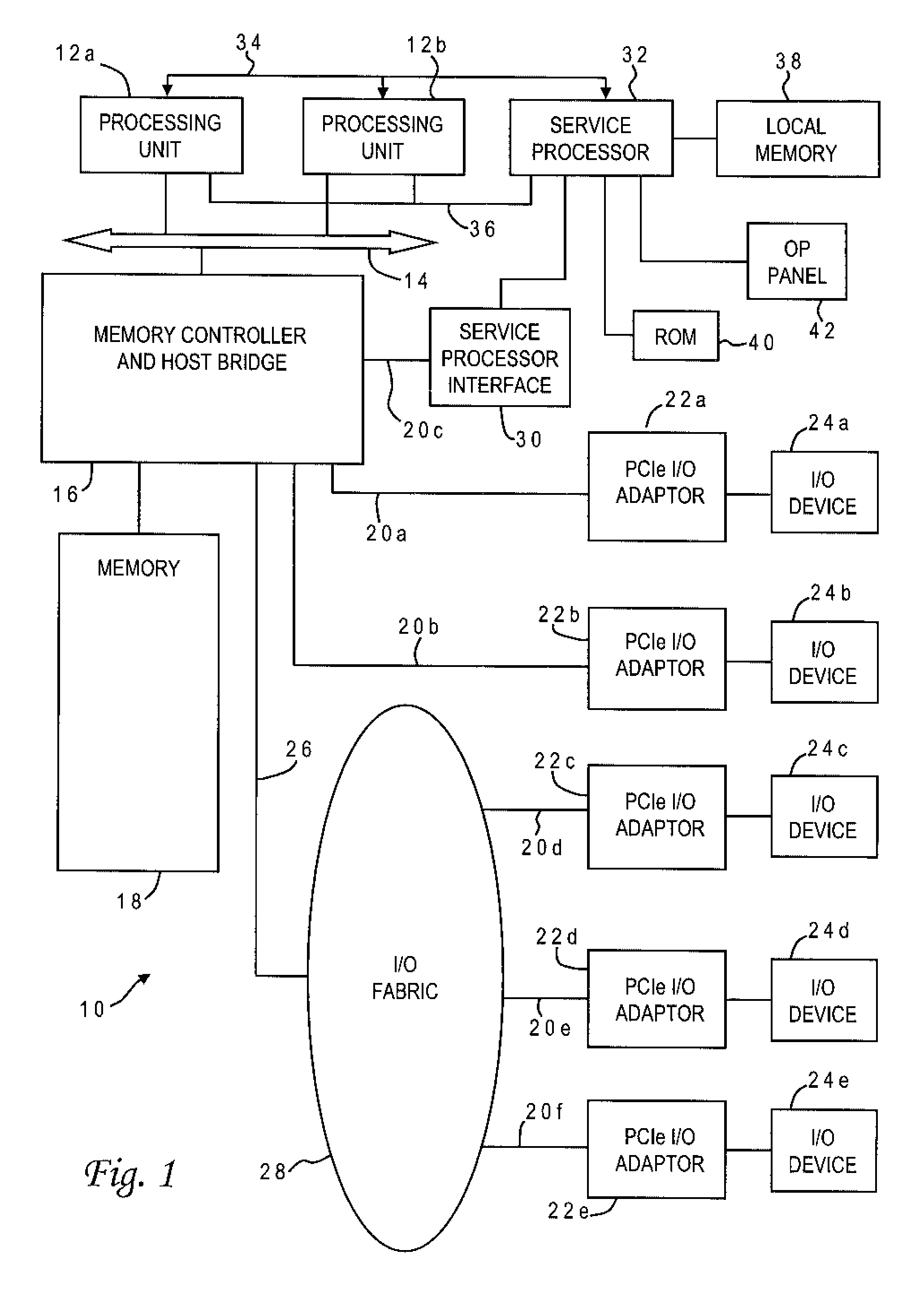
[0021]With reference now to the figures, and in particular with reference to FIG. 1, there is depicted one embodiment 10 of a computer system constructed in accordance with the present invention. Computer system 10 is a symmetric multiprocessor (SMP) system having a plurality of processors 12a, 12b connected to a system bus 14. System bus 14 is further connected to a combined memory controller / host bridge (MC / HB) 16 which provides an interface to system memory 18. System memory 18 may be a local memory device or alternatively may include a plurality of distributed memory devices, preferably dynamic random-access memory (DRAM). There may be additional structures in the memory hierarchy which are not depicted, such as on-board (L1) and second-level (L2) or third-level (L3) caches. In the illustrative implementation, computer system 10 is a server. Any of the components of server 10, and in particular processors 12a, 12b, may be provided as field-replaceable units. While only two proc...


PUM


Abstract

A performance measure (e.g., processor speed) for computing components such as servers is optimized by creating models of power consumption versus the performance measure for each server, adding the power models to derive an overall power model, and calculating an optimum set point for the performance measure which corresponds to a power limit on the servers using the overall power model. The set point is then used to set power budgets for the servers based on their power models, and the servers maintain power levels no greater than their respective power budgets. The server power models are preferably created in real time by monitoring power consumption and the performance measure to derive sets of data points for the servers, and performing regression on the sets of data points to yield power models for the servers. Multiple server power models may be created for different program applications.

Description

BACKGROUND OF THE INVENTION[0001]1. Field of the Invention[0002]The present invention generally relates to computer systems, and more specifically to methods and systems for power management of high performance computing centers such as server systems having multiple servers which work together to carry out program applications.[0003]2. Description of the Related Art[0004]Power management has become a dominant concern in the development of data processing systems and the design of data center facilities. In recent years, a trend in server design is to make the servers physically smaller and pack them densely in a rack. A typical format is the blade server. Several blade servers share common power, cooling, network, and I / O infrastructure from a single blade chassis. This construction allows these shared components to largely be removed from the blade design and allows computing components such as microprocessors and dynamic random access memory (DRAM), both of which consume large am...

Claims


Application Information

Patent Timeline
IPC IPC(8): G06F1/00G06F9/44
CPCG06F1/3203G06F9/5027Y02B60/142G06F9/5094G06F9/5083Y02D10/00
Inventor BLETSCH, TYLER K.FELTER, WESLEY M.GAZALA, NEVEN A.HORVATH, TIBORLEFURGY, CHARLES R.
Owner IBM CORP
Why Eureka
Try Eureka