Ingeeni flash interface

Inactive Publication Date: 2005-06-30
HLAVAC MICHAL +5
View PDF2 Cites 18 Cited by
  • Summary
  • Abstract
  • Description
  • Claims
  • Application Information

AI Technical Summary

Benefits of technology

[0012] 3D graphics systems of the type described above are preferred in many applications, inasmuch as they provide a robust graphics environment able to produce highly realistic images. Unfortunately, however, such 3D graphics systems also have some significant disadvantages associated with them, including computational requirements, large file size, etc. Some of these disadvantages can become prohibitive where data must be transferred across a network (e.g., the Internet) and images rendered on a client computer, particularly where the client computer may have a relatively slow network connection and/or limited processing power.
[0013] As a result, some 2D graphics systems have been developed which may be used even where there is a relatively slow network connection and/or limited client processing power. Macromedia's Flash system is an example of one such system which is currently in widespread use. With the Flash system, a Flash player is installed on the client computer and relatively modest data files must be sent over the network. Unfortunately, the Flash system is

Problems solved by technology

Some Disadvantages of 3D Graphics Systems
Unfortunately, however, such 3D graphics systems also have some significant disadvantages associated with them, including computational requirements, large file size, etc.
Some of these disadvantages can become prohibitive where data must be transferred across a network (e.g., the Internet) and images rendered on a client computer, particularly where the client computer may have a relatively slow network connection and / or limited processing power.
Unfortunately, the Flash system is based on 2D graphics, which generally provides a less robust user experience than 3D graphics.

Method used


Image

  • Ingeeni flash interface
  • Ingeeni flash interface
  • Ingeeni flash interface

Examples


Embodiment Construction

NEW—How the Ingeeni Solution Works

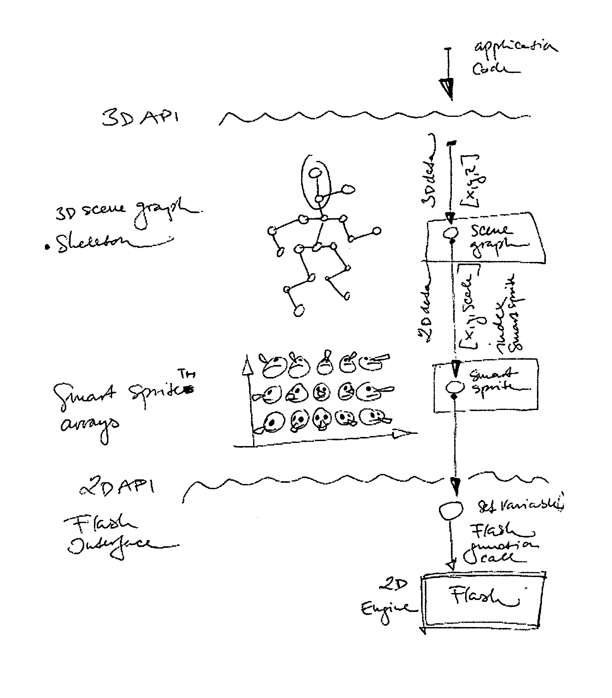
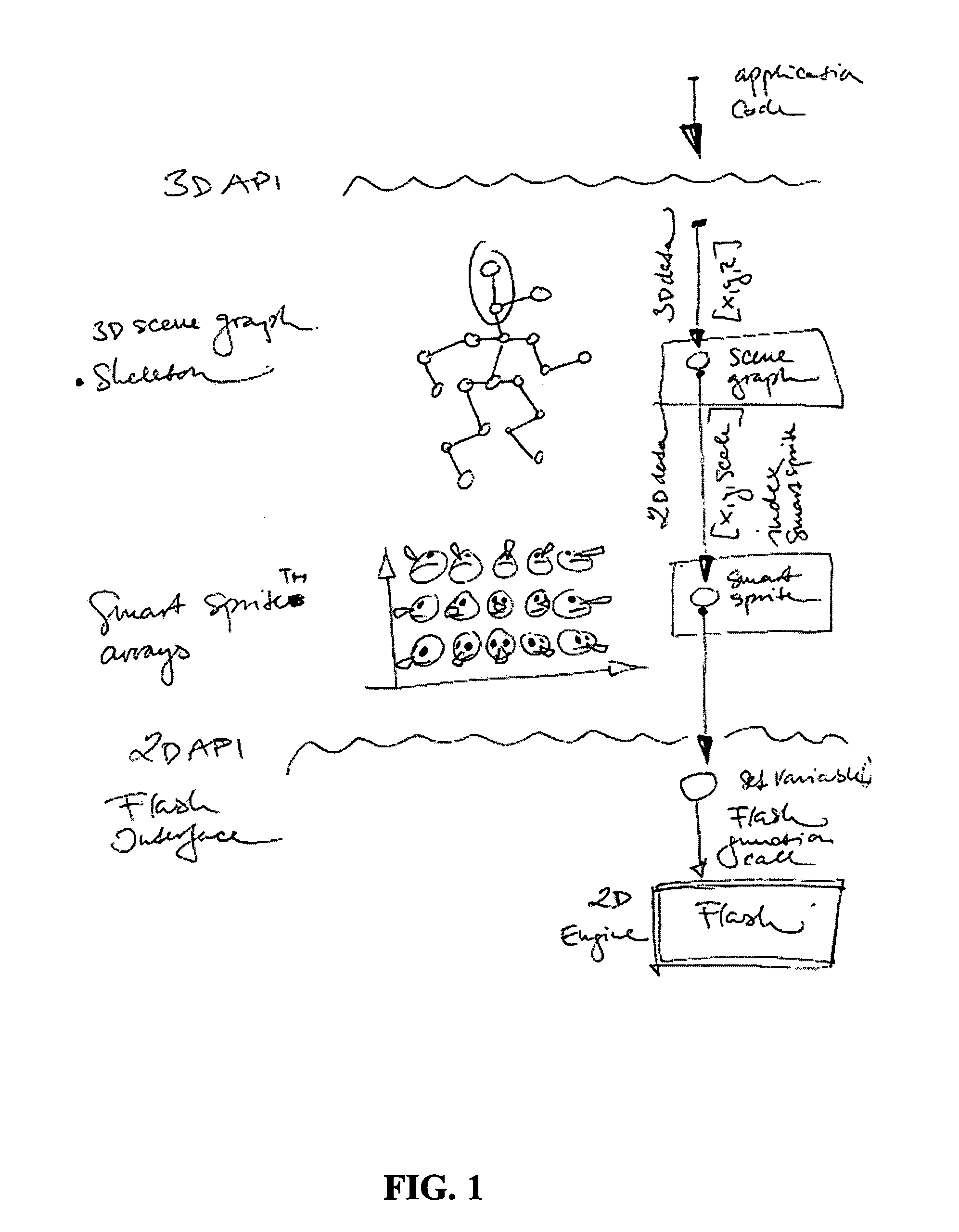
[0037] As noted above, the present invention relates to an adapter which sits between a 3D graphics system and a 2D graphics system so as to provide the best advantages of each system.

[0038] As also noted above, one such 2D system currently in widespread use is the Macromedia Flash system.

[0039] Inasmuch as the present invention is particularly well suited to use with the Macromedia Flash system, and inasmuch as the Macromedia Flash system is currently in widespread use, the following description will be delivered in the context of the Macromedia Flash system. However, it should be appreciated that this is solely for the sake of example and not limitation. The present invention is also applicable to use with many other 2D graphics systems.

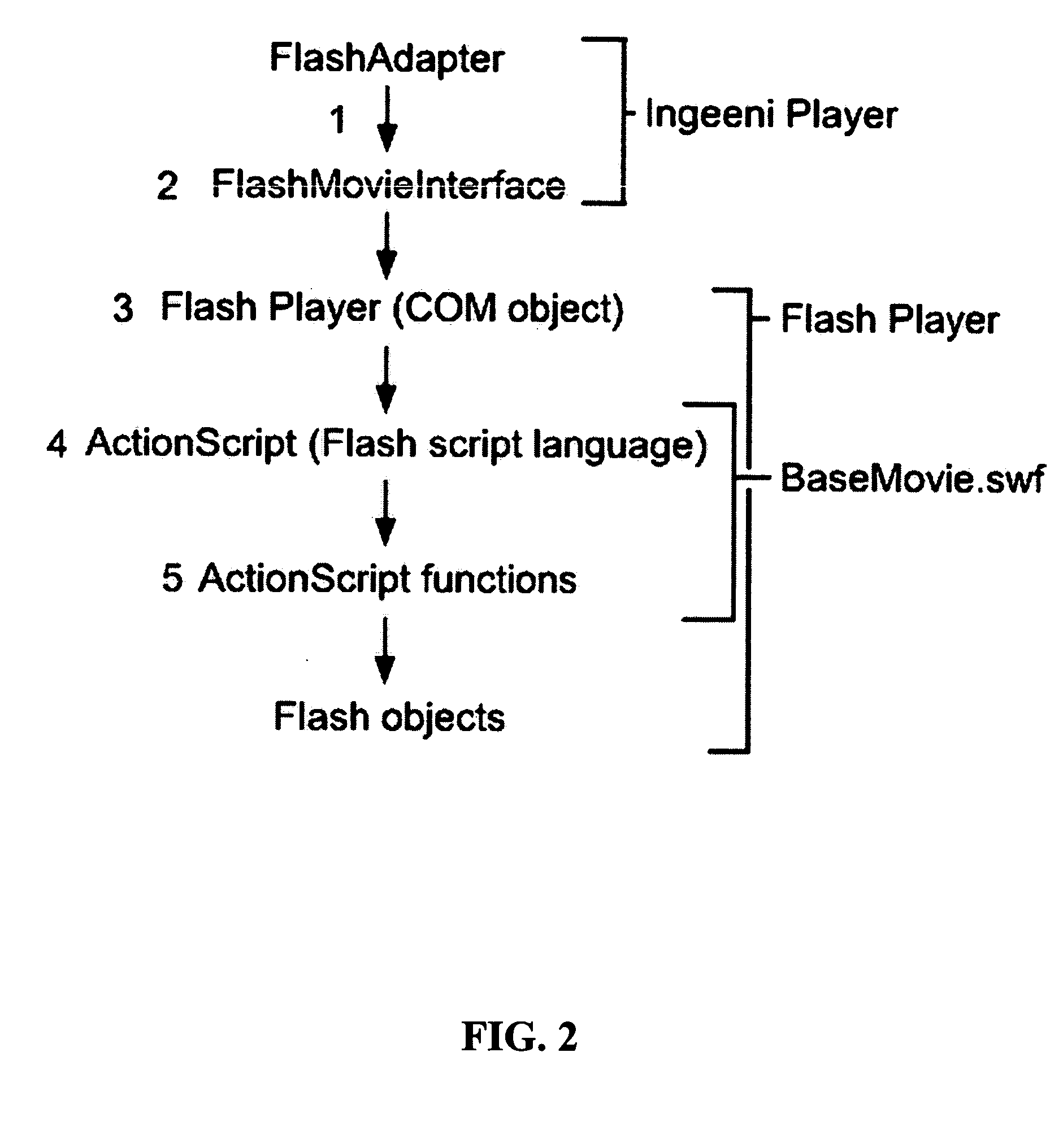
[0040] Ingeeni has created the FlashAdapter to sit as an interface between a 3D graphics system and the Flash player. The following is a description of how the Ingeeni FlashAdapter sets up the communication chan...


PUM


Abstract

A method for presenting graphics to a user is disclosed, the method comprising providing a 3D graphics system comprising a 3D graphics environment and at least one virtual object positioned in the 3D graphics environment, providing a 2D graphics rendering engine configured to use 2D mathematics, and providing a library of sprites for use by the 2D graphics rendering engine, selecting a camera perspective within the 3D graphics environment, based on the selected camera perspective, generating an appropriate 2D view of the 3D graphics environment, based on the generated 2D view, selecting an appropriate sprite and, for that sprite, the appropriate rendered view for that sprite, determining the appropriate screen location and scale for the selected rendered view for the sprite, and instructing the 2D graphics rendering engine to paint the selected rendered view for the sprite to the determined screen location and with the determined scale.

Description

REFERENCE TO PENDING PRIOR PATENT APPLICATIONS [0001] This patent application claims benefit of pending prior U.S. Provisional Patent Application Ser. No. 60 / 532,969, filed Dec. 29, 2003 by Michal Hlavac et al. for INGEENI FLASH INTERFACE (Attorney's Docket No. INGEENI-4 PROV), which patent application is hereby incorporated herein by reference.FIELD OF THE INVENTION [0002] This invention relates to computer graphics in general, and more particularly to a novel system for presenting 3D graphics using a 2D graphics rendering engine. Among other things, the present invention may be applied to computer graphics systems for presenting animated characters and the like. BACKGROUND OF THE INVENTION [0003] In many situations, it may be desirable to present images of 3D objects on a television or computer screen. These 3D objects may comprise substantially any type of object, including real objects and imaginary objects. [0004] One type of object which may be presented is that of animated ch...

Claims


Application Information

Patent Timeline
IPC IPC(8): G06T13/00G06T15/00
CPCG06T13/00G06T2213/04G06T15/005
Inventor HLAVAC, MICHALMAYMIN, SENIAHLAVAC, MILOSBREAZEAL, CYNTHIAHLAVAC, JURAJBROMLEY, DENNIS
Owner HLAVAC MICHAL
Why Eureka
Try Eureka