Ear-attaching type electronic device and biological information measuring method in ear-attaching type electronic device

a biological information and electronic device technology, applied in the field of biological information measuring method in the ear-attaching type electronic device, can solve the problems of easy disengagement, troublesome exercise, and difficulty in occasionally measuring pulse during exercis

Inactive Publication Date: 2005-06-30
CASIO COMPUTER CO LTD
View PDF5 Cites 41 Cited by
  • Summary
  • Abstract
  • Description
  • Claims
  • Application Information

AI Technical Summary

Problems solved by technology

However, with this method, it is necessary to contact a finger to the wristwatch at each time of measuring pulse, and therefore it is difficult to occasionally measure pulse during the exercise.
Therefore, the cable floats during exercise, whereby, it bothers the exercise, for example, it bothers a swinging arm at the time of jogging.
Further, since a posture of the headphone at the time of attachment is maintained only according to elasticity corresponding to the bending of an arm part, there is the case that the arm part goes out of alignment or gets disengaged easily due to the movement of user's body, especially the movement of a head part.
Accordingly, its attaching operation and sense of the attachment are bothersome.
Therefore, it is extremely inconvenient.
Therefore, while listening to the music or the radio, it is not possible to hear pitch sound from the measuring device.
To the contrary, while hearing pitch sound from the measuring device, it is not possible to listen to the music or the radio.
Therefore, it is extremely inconvenient.
However, if such a headphone type measuring device is folded to be housed, the code gets wrenched according to the rotation of the arm part with respect to the body part, and there is a possibility of breaking the code.

Method used


Image

  • Ear-attaching type electronic device and biological information measuring method in ear-attaching type electronic device
  • Ear-attaching type electronic device and biological information measuring method in ear-attaching type electronic device
  • Ear-attaching type electronic device and biological information measuring method in ear-attaching type electronic device

Examples


first embodiment

[1-1 External Structure]

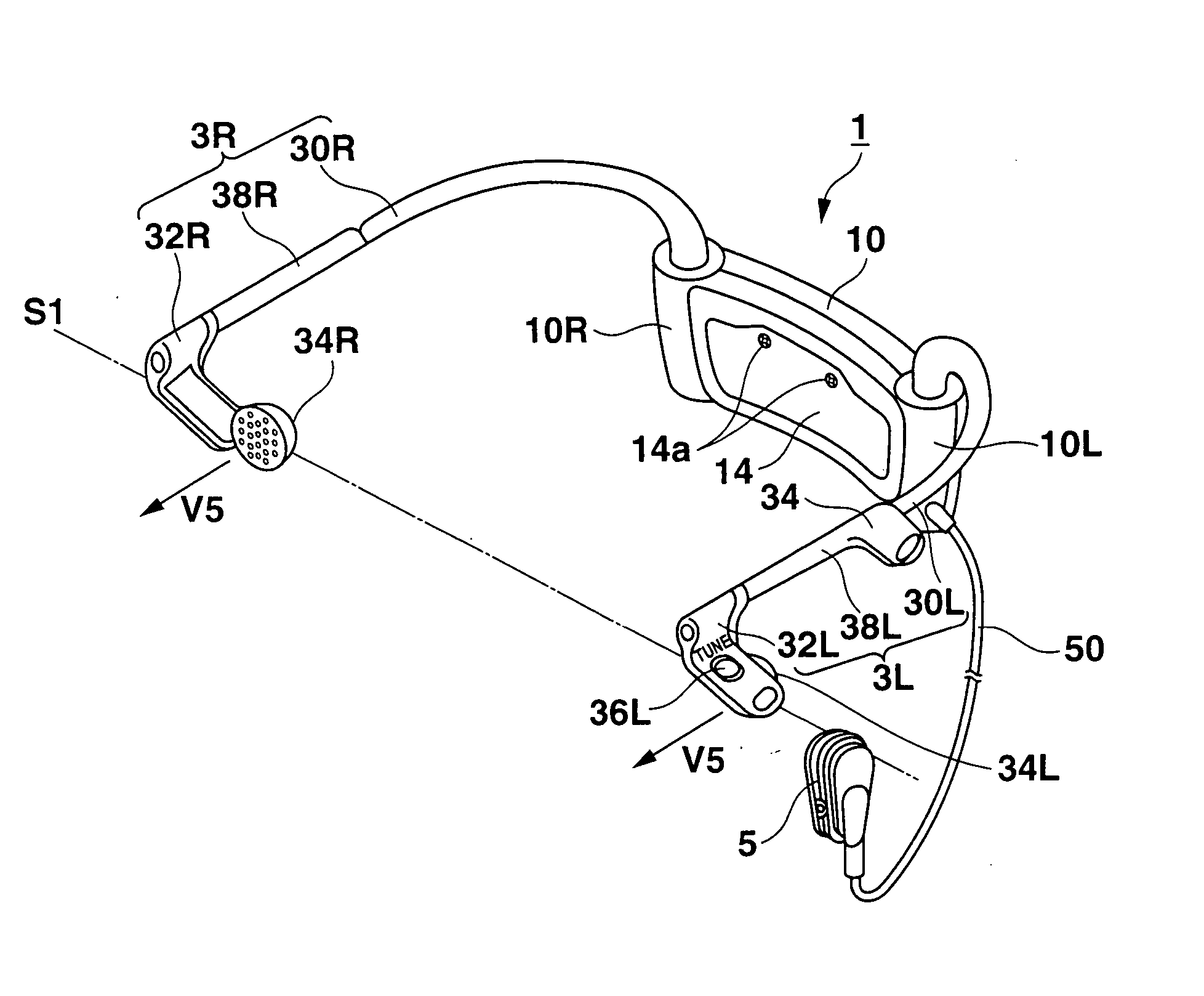
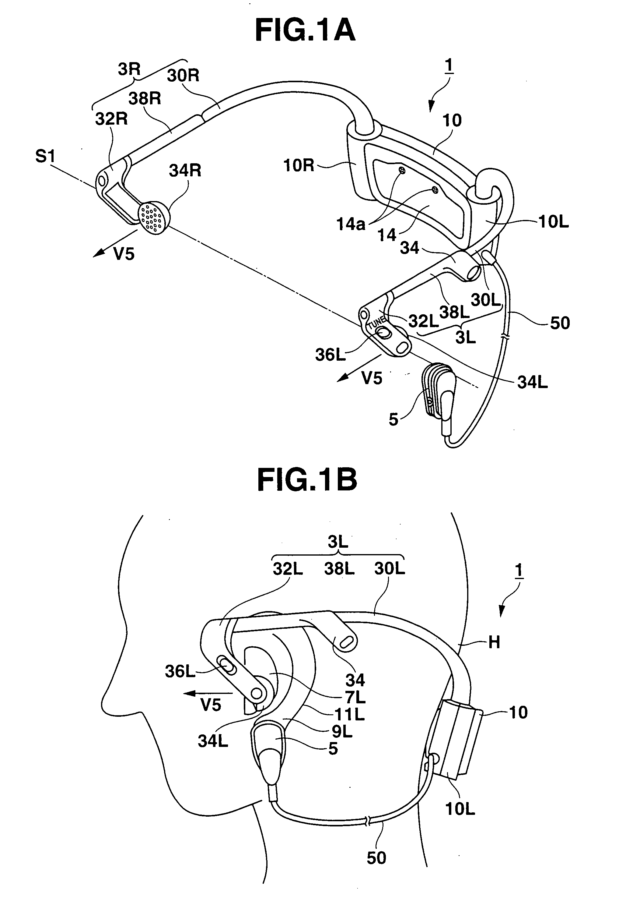
[0065] Hereinafter, a first embodiment of the case that an ear-attaching type electronic device of the present invention is applied to an ear-attaching type pulse measuring device (hereafter, it is referred to as “ear-attaching type device”) 1 will be described with reference from FIG. 1A to FIG. 13.

[0066] Here, directions under the description are assumed to be the directions with respect to a user who attaches the ear-attaching type device 1 to himself / herself. Concretely, it is assumed that a face side when attaching the ear-attaching type device 1 (toward left in FIG. 1B) is front, an occipital side (toward right in FIG. 1B) is back, a left ear side is left, a right ear side is right, an up side is up, and a down side is down. Further, it is assumed that a direction in which left and right arm parts 3R and 3L are facing, that is, a direction toward the center of a head part is an internal direction, and its opposite direction is an external direction.

[...

second embodiment

[0199] Next, a second embodiment to which the present invention is applied will be described. The present embodiment is to change an interval of pitch sound which is outputted according to a pulse rate at exercising (heartbeat at exercising) according to whether it is within, above or below a set range, in order to achieve appropriate exercise.

[2-1 Structure]

[0200]FIG. 23A is a block diagram showing an ear-attaching type device 1 incorporating therein a pulse measuring function. As shown in FIG. 23A, the ear-attaching type device 1 comprises a CPU 100, a ROM 102, a RAM 104, a pulse measuring unit 108, a pulse sensor unit 5, a vibration measuring unit 106, a radio reception circuit unit 114, an inputting unit 110, a displaying unit 112, a sound outputting unit 116, and a signal data line 120. Hereinafter, the same numerals are added to the same components as the first embodiment and the description thereof is omitted. Further, in each flowchart, the same numerals are added to steps...

third embodiment

[0240] With reference to FIG. 30, an ear-attaching type device 1 in the third embodiment will be described in detail.

[0241] Here, FIG. 30 is a magnified view showing a right arm supporting member 10R for describing a biasing mechanism in the ear-attaching type device in the third embodiment of the present invention.

[0242] Here, in the third embodiment, while description regarding the biasing mechanism in the ear-attaching type device 1 is made, since everything other than the biasing mechanism is the same as the first embodiment, the description thereof is omitted.

[0243] In the ear-attaching type device in the third embodiment, the right arm part 3R is supported by the biasing mechanism in the body part 10 so as to bias the right arm part 3R at the right upper edge part of the body part 10 in the internal direction, and the left arm part 3L is supported so as to bias the left arm part 3L at the left upper edge part of the body part 10 in the internal direction (arrow V3).

[0244] ...


PUM


Abstract

An ear-attaching type electronic device includes: a body part supported in a vicinity of a lower part of an occipital part when the device is attached; a pair of arm parts extending from the body part, to which a connecting member is placed therein; and a pulse sensor section for detecting pulse by being attached to an earlobe, wherein advice is outputted according to a comparison between a detected pulse rate and a previously-set pulse rate range.

Description

CROSS-REFERENCE TO RELATED APPLICATIONS [0001] This application is based upon and claims the benefit of priority from the prior Japanese Patent Application No. 2003-434069, filed Dec. 26, 2003, and 2003-434881, filed Dec. 26, 2003, and 2004-295995, filed Oct. 08, 2004, and the entire contents of which are incorporated herein by reference. BACKGROUND OF THE INVENTION [0002] 1. Field of the Invention [0003] The present invention relates to an ear-attaching type electronic device and a biological information measuring method in the ear-attaching type electronic device, the ear-attaching electronic device being structured to be capable of measuring biological information and outputting sound simultaneously. [0004] 2. Description of Related Art [0005] Conventionally, a measuring device which measures biological information regarding bloodstream of a human body, such as pulse, heart rate and the like, is known. Such an measuring device is not only used as a medical device, but is also wid...

Claims


Application Information

Patent Timeline
Patent Type & Authority Applications(United States)
IPC IPC(8): A61B5/024
CPCA61B5/02438A61B5/6816A61B5/6815
Inventor KANZAKI, TAKASHINIIMI, MASAZUMI
Owner CASIO COMPUTER CO LTD
Why Eureka
Try Eureka