Fuel cell and membrane electrode assembly

a technology of membrane electrodes and fuel cells, applied in the direction of active material electrodes, cell components, electrochemical generators, etc., can solve the problems of limited site for proper construction, depletion of energy resources such as oil, and environmental pollution, so as to improve catalytic activity and increase catalyst surface area

Inactive Publication Date: 2005-06-30
HITACHT MAXELL LTD
View PDF4 Cites 60 Cited by
  • Summary
  • Abstract
  • Description
  • Claims
  • Application Information

AI Technical Summary

Problems solved by technology

However, thermal power generation burns fossil fuels such as oil and coal and it causes not only extensive environmental pollution but also a depletion of energy resources such as oil.
The use of water power generation requires large-scale dam construction so that the number of sites for proper construction are limited.
Also, the building of the dam and the change in water coverage of the land can cause destruction of nature.
Further, the nuclear electric power generation has problems including the fact that radioactive contamination is possible in the event of an accident which can be fatal and decommissioning of nuclear reactor facility is difficult.
These problems have resulted in the decrease of nuclear reactor construction on a global basis.
However, wind power generation cannot generate power with no wind and the solar photovoltaic power generation cannot generate power with no sunlight.
The two systems are dependent on natural phenomena, and thus, are incapable of providing a stable power supply.
Further, the wind power generation has a problem that the frequency of generated power varies with the intensity of wind, causing breakdown of the electrical equipment.
Since the oxidation-reduction reaction has a high thermodynamic barrier making it difficult to achieve at room temperature, a catalyst is used in the fuel cells.
However, since the organic protective agent absorbs onto the surface of the Pt catalyst in this technique, it is necessary to remove the organic protective agent from the surface of the Pt catalyst to show its catalytic activity.
However, this treatment cannot completely remove the organic protective agent from the Pt catalyst surface.
Further, the heat treatment at 400° C. can cause sintering of the Pt particulates, which results in an increase in the catalyst particle size and a decrease in the catalytic activity.
Furthermore, it is possible for chemisorption to occur of carbon monoxide (CO) generated during the methanol oxidation process or contained in the hydrogen gas onto the Pt catalyst at the anode, which results in deactivation of catalytic activity.
If the Pt—Ru particle size remains large, the effective catalyst surface area does not increase and the catalytic activity stays unimproved.
In this case, the technique of adding the organic protective agent to reduce the Pt—Ru catalyst particle size is not available for the above reasons.
A new effective technique to produce a Pt—Ru catalyst for the anode of less than 5 nm has thus been strongly required, but it remains unachieved.
In this case, the technique of adding the organic protective agent to reduce the Pt catalyst particle size is not available for the above reasons.
Anew effective technique to produce a Pt catalyst for the cathode less than 5 nm has thus been strongly required, but it remains unachieved.

Method used

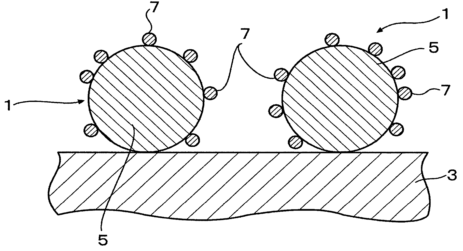
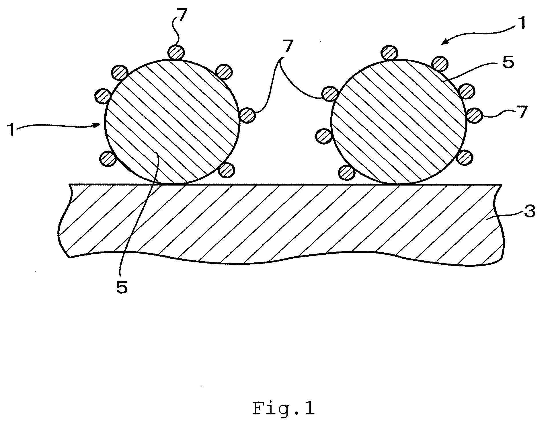
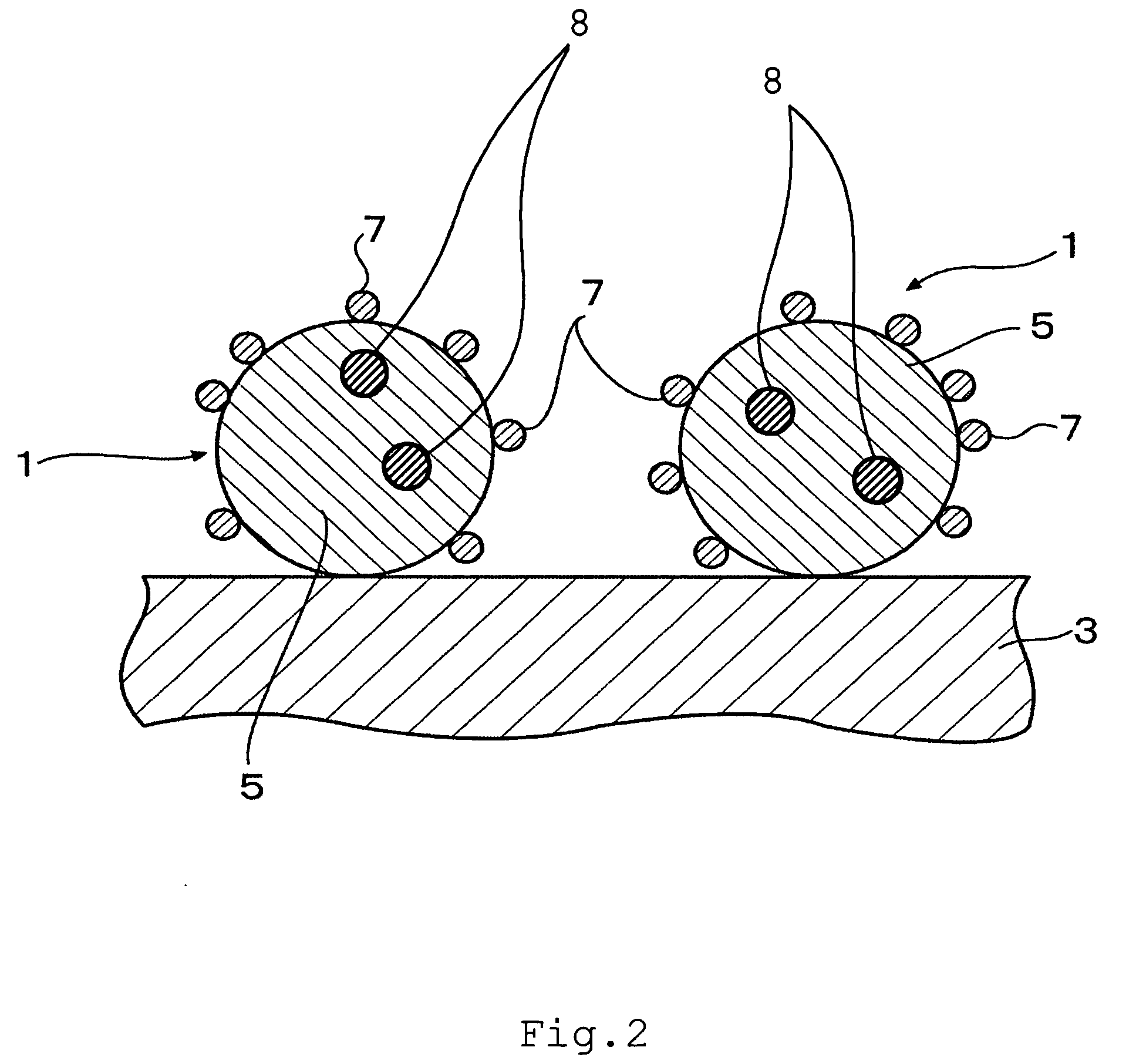

Image

  • Fuel cell and membrane electrode assembly
  • Fuel cell and membrane electrode assembly
  • Fuel cell and membrane electrode assembly

Examples


example 1

[0063] Bis(acetylacetonato)platinum(II) of 1.69 mmol, tris(acetylacetonato) ruthenium(III) of 1.69 mmol, and sodium phosphinate of 0.338 mmol were dissolved into ethylene glycol of 300 ml. An ethylene glycol solution of 100 ml into which a carbon support of 0.5 g (Vulcan XC-72R available from E-TEK Inc., Somerset, N.J., with the specific surface area of 254 m2 / g) was dispersed was added thereto. A sulfuric acid solution was added, and the pH value of the solution was adjusted to 3 using a pH litmus paper. In a nitrogen gas atmosphere, the solution was stirred and refluxed for 4 hours at 200° C., thereby depositing Pt—Ru—P catalyst particulates on the carbon support. Subsequent filtration, washing, and drying gave a catalyst.

example 2

[0064] Bis(acetylacetonato)platinum(II) of 1.69 mmol, tris(acetylacetonato) ruthenium(III) of 1.69 mmol, and sodium dihydrogenphosphite of 0.338 mmol were dissolved into ethylene glycol of 300 ml. An ethylene glycol solution of 100 ml into which a carbon support of 0.5 g (Vulcan XC-72R with the specific surface area of 254 m2 / g) was dispersed was added thereto. A sulfuric acid solution was added, and the pH value of the solution was adjusted to 3 using a pH litmus paper. In a nitrogen gas atmosphere, the solution was stirred and refluxed for 4 hours at 200° C., thereby depositing Pt—Ru—P catalyst particulates on the carbon support. Subsequent filtration, washing, and drying gave a catalyst.

example 3

[0074] An alcohol solution of pure water and NAFION® dispersion solution, available from E.I. DuPont de Nemours and Company, Wilmington, Del., was added to the Pt—Ru—P catalyst deposited on the Vulcan XC-72R obtained in inventive example 1 and stirred, and then its viscosity was adjusted to create a catalyst ink. The catalyst ink was then applied onto TEFLON® sheet, available also from Dupont, in such a way that the amount of the Pt—Ru—P catalyst is 5 mg / cm2. After being dried, the TEFLON® sheet was peeled off, thereby creating a methanol electrode catalyst. Further, an alcohol solution of pure water and NAFION® dispersion solution was added to the Pt catalyst deposited on Ketjen EC, available from Ketjen Black International. Co., Tokyo, Japan, and stirred, and then its viscosity was adjusted to create a catalyst ink. The catalyst ink was then applied onto TEFLON® sheet in such a way that the amount of the Pt catalyst is 5 mg / cm2. After being dried, the TEFLON® sheet was peeled off,...


PUM

PropertyMeasurementUnit
particle diameteraaaaaaaaaa
diameteraaaaaaaaaa
specific surface areaaaaaaaaaaa

Abstract

A fuel cell has an anode, a cathode, and a polymer electrolyte membrane placed between the anode and the cathode. The anode includes a catalyst which is composed of binary or ternary particulates deposited on a carbon support. The particulate is represented by a general formula: Pt—P, wherein Ru is optionally present. The content of P is in a range of 2 mol % to 50 mol % based on the total moles of Pt or Pt—Ru. The diameter of the catalyst particulates is in range from 1 to 3 nm.

Description

CROSS-REFERENCE TO RELATED APPLICATION [0001] The present application claims priority to Japanese Patent Application Serial No. 2003-433758, and Japanese Patent Application Serial No. 2004-206232 which are both hereby incorporated by reference in their entirety. BACKGROUND OF THE INVENTION [0002] 1. Field of the Invention [0003] The present invention relates to fuel cells and membrane electrode assemblies having a new catalyst at an electrode. More specifically, the present invention relates to fuel cells and membrane electrode assemblies comprising a platinum and phosphorus catalyst at either a fuel electrode / anode or cathode. [0004] 2. Description of Related Art [0005] For the most part, electric energy has been supplied by thermal power generation, water power generation, and nuclear electric power generation. However, thermal power generation burns fossil fuels such as oil and coal and it causes not only extensive environmental pollution but also a depletion of energy resources ...

Claims


Application Information

Patent Timeline
Patent Type & Authority Applications(United States)
IPC IPC(8): H01M4/86H01M4/88H01M4/92H01M8/10
CPCB82Y30/00H01M4/8605H01M4/921Y02E60/522H01M8/1004Y02E60/523H01M4/923Y02E60/50
Inventor DAIMON, HIDEOYAMAMOTO, YUKIKO
Owner HITACHT MAXELL LTD
Why Eureka
Try Eureka