Polymer electrolyte membrane and solid polymer electrolyte fuel cell using same

a technology of electrolyte and polymer, which is applied in the direction of non-aqueous electrolyte cells, cell components, sustainable manufacturing/processing, etc., can solve the problems of poor adhesion and achieve the effect of excellent performance in generating electricity

Inactive Publication Date: 2005-08-23
HONDA MOTOR CO LTD +1
View PDF9 Cites 76 Cited by
  • Summary
  • Abstract
  • Description
  • Claims
  • Application Information

AI Technical Summary

Benefits of technology

[0018]It is an object of the present invention to present a solution to the first disadvantage mentioned above by providing a cheap composite polymer electrolyte membrane which permits of excellent adhesion to the electrodes when employed in a solid polymer electrolyte fuel cell, and a solid polymer electrolyte fuel cell which utilizes the composite polymer electrolyte membrane.
[0019]It is a further object of the present invention to present a solution to the second disadvantage mentioned above by providing a composite polymer electrolyte membrane which exhibits excellent mechanical strength when employed in a solid polymer electrolyte fuel cell, and permits of excellent performance in generating electricity irrespective of changes in temperature and humidity, along with a method of manufacturing the composite polymer electrolyte membrane.
[0020]It is yet another object of the present invention to present a solution to the third disadvantage mentioned above by providing an membrane electrode assembly which can be manufactured cheaply and exhibits excellent properties of heat resistance, along with a solid polymer electrolyte fuel cell which utilizes the membrane electrode assembly and exhibits excellent performance in generating electricity even under conditions of high temperature.

Problems solved by technology

They believe that if a material of this sort is employed in the polymer electrolyte membrane of a solid polymer electrolyte fuel cell, the polymer electrolyte membrane becomes detached from the electrodes by virtue of repeated dilation, expansion and contraction due to the high temperature experienced while the fuel cell is in operation and the low temperature experienced when it is not, the result being poor adhesion.

Method used


Image

  • Polymer electrolyte membrane and solid polymer electrolyte fuel cell using same
  • Polymer electrolyte membrane and solid polymer electrolyte fuel cell using same
  • Polymer electrolyte membrane and solid polymer electrolyte fuel cell using same

Examples


working examples 13-15

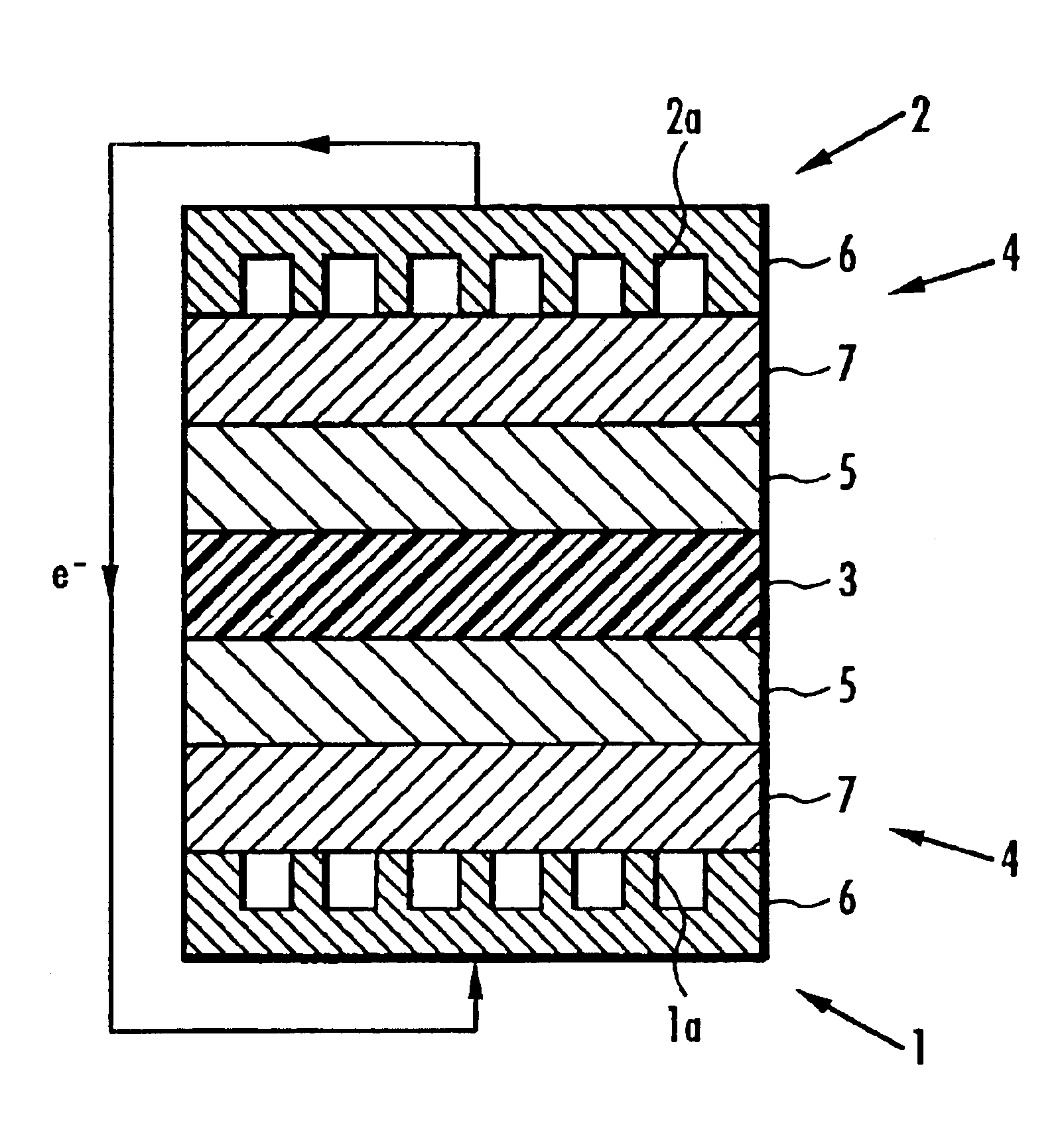
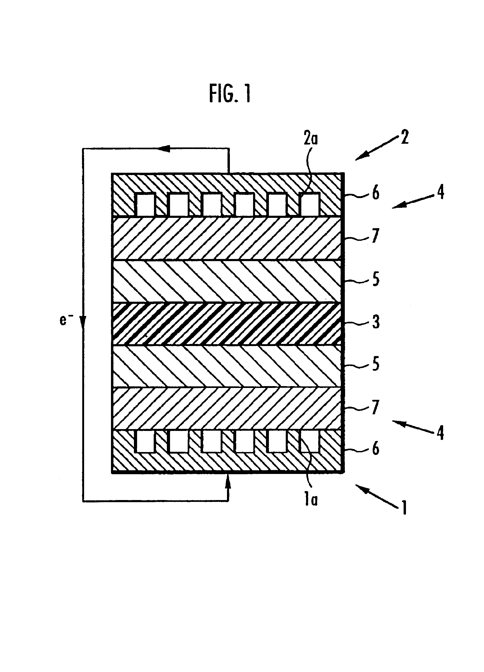
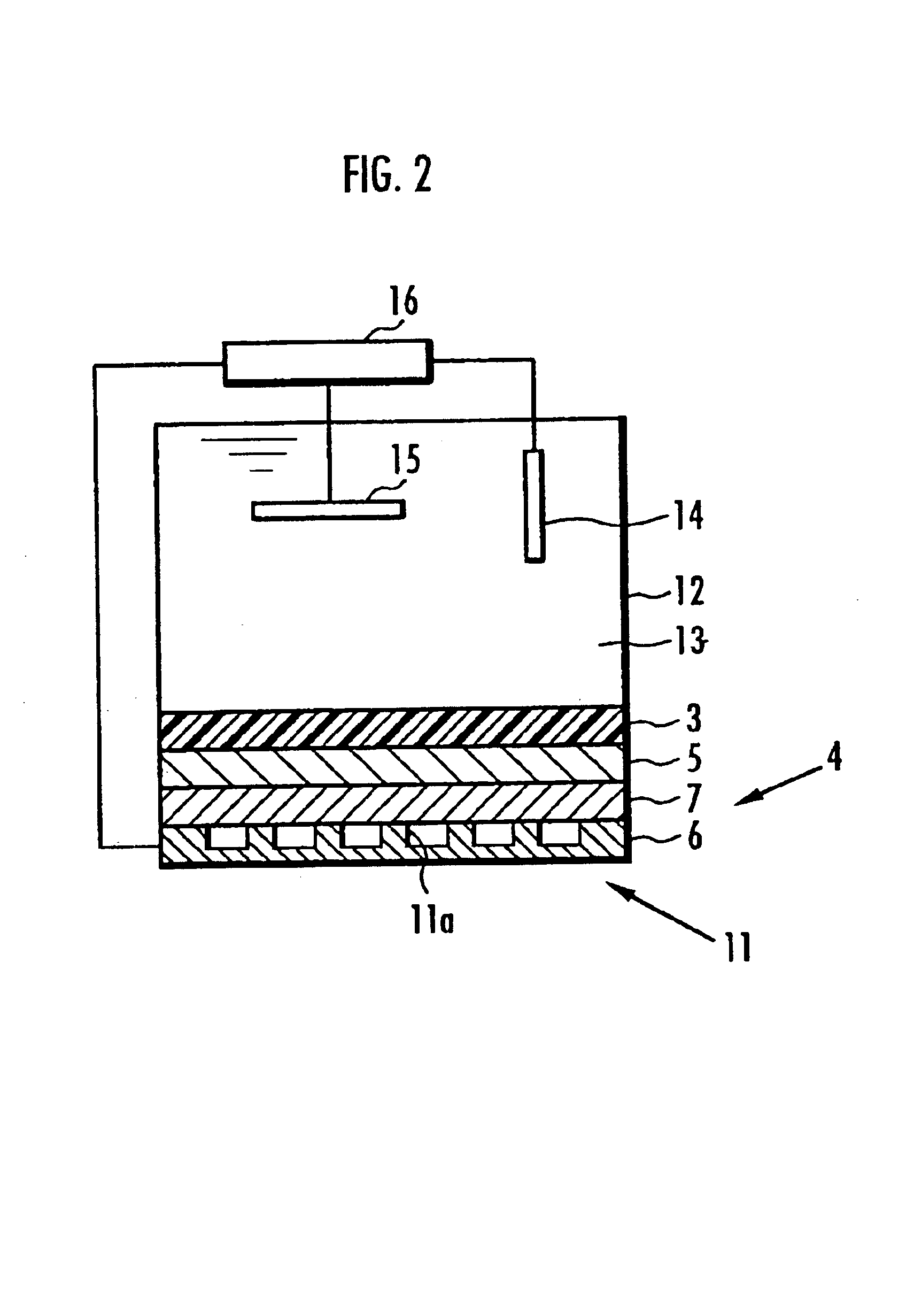
[0552]Next, 5-15 mol 4,4′-dichlorobenzophenone as monomer A constituting the first polymer electrolyte was used with 85-95 mol 2,5-dichloro-4-phenoxybenzophenone as monomer B to manufacture composite polymer electrolyte membranes 3 in exactly the same manner as in Working examples 7-12 except that the molar ratio of the constituents of the first polymer electrolyte was varied, and the ratio by weight of the first polymer electrolyte to the second was 85:15.

[0553]Solid polymer electrolyte fuel cells were manufactured in exactly the same manner as in Working Examples 1-6 except for the use of different composite polymer electrolyte membranes 3. The electric charge per unit area of the membrane electrode assembly (Q value), generated potential and resistance to hot water of the solid polymer electrolyte fuel cells employing the composite polymer electrolyte membrane 3 were measured in exactly the same manner as in Working Examples 1-6, and their performance compared. The results are sh...

working examples 16-18

[0556]Next, 2-15 mol 4,4′-bis(4-chlorobenzoyl)diphenylether was used in place of 4,4′-dichlorobenzophenone as monomer A constituting the first polymer electrolyte with 85-98 mol 2,5-dichloro-4-phenoxybenzophenone as monomer B to manufacture composite polymer electrolyte membranes 3 in exactly the same manner as in Working examples 7-12 except that the molar ratio of the constituents of the first polymer electrolyte was varied, and the ratio by weight of the first polymer electrolyte to the second was 85:15.

[0557]Solid polymer electrolyte fuel cells were manufactured in exactly the same manner as in Working examples 1-6 except for the use of different composite polymer electrolyte membranes 3. The electric charge per unit area of the membrane electrode assembly (Q value), generated potential and resistance to hot water of the solid polymer electrolyte fuel cells employing the composite polymer electrolyte membrane 3 were measured in exactly the same manner as in Working examples 1-6,...

working example 19

[0562]To begin with, 4,4′-dichlorobenzophenone as monomer A corresponding to the aromatic compound unit with an electron-attractive group in its principal chain and 2,5-dichloro-4-phenoxybenzophenone as monomer B corresponding to the aromatic compound unit without an electron-attractive group in its principal chain were dissolved in N-methylpyrrolidone in a molar ratio of 1:9. The resultant solution was fed together with a catalyst system comprising sodium iodide, bistriphenylphosphinenickel dichloride, triphenylphosphine and zinc into a three-necked flask which was fitted with a reflux pipe and three-way stopcock, the air within the flask having been replaced with nitrogen. Monomers A and B were heated together inside the three-necked flask in a nitrogen environment within an oil bath at 70° C. to polymerize them. The composition of the catalyst system in relation to the sum total of monomers A and B was 13 mol % sodium iodide, 3 mol % bistriphenylphosphinenickel dichloride, 40 mol...


PUM

PropertyMeasurementUnit
wt %aaaaaaaaaa
wt %aaaaaaaaaa
mol %aaaaaaaaaa

Abstract

A composite polymer electrolyte membrane is formed from a first polymer electrolyte comprising a sulfonated polyarytene polymer and a second polymer electrolyte comprising another hydrocarbon polymer electrolyte. In the first polymer electrolyte, 2-70 mol % constitutes an aromatic compound unit with an electron-attractive group in its principal chain, while 30-98 mol % constitutes an aromatic compound unit without an electron-attractive group in its principal chain. The second polymer electrolyte is a sulfonated polyether or sulfonated polysulfide polymer electrolyte.

Description

DETAILED DESCRIPTION OF THE INVENTION[0001]1. Field of the Invention[0002]The present invention relates to a polymer electrolyte membrane and to a solid polymer electrolyte fuel cell using the same.[0003]2. Background of the Invention[0004]The world of today is faced with grave environmental issues: on the one hand oil reserves are becoming exhausted, while on the other the use of fossil fuel leads to global warming. Attention is focused on fuel cells as a clean source of power for electric motors which does not involve the emission of carbon dioxide, and they are currently being widely developed. Indeed, such fuel cells have been put to practical use in certain fields. When it comes to their application in motor cars and the like, solid polymer electrolyte fuel cells employing polymer electrolyte membranes are eminently suitable on account of the ease of acquiring high voltage and current.[0005]Solid polymer electrolyte fuel cells comprise an ion-permeable polymer electrolyte membr...

Claims


Application Information

Patent Timeline
Patent Type & Authority Patents(United States)
IPC IPC(8): B01D69/10B01D69/14B01D71/00B01D69/00B01D71/52B01D71/72B01D71/82C08J5/20C08J5/22C08L65/00H01M8/10C08L71/00H01M4/86
CPCB01D69/10B01D69/141B01D71/52B01D71/72B01D71/82C08J5/2256C08J5/2275C08L65/00H01M8/1004H01M8/1025H01M8/1044H01M8/1081C08L71/00H01M4/8605Y02E60/521C08L2666/14C08J2381/08Y02P70/50B01D69/1411B01D69/1071B01D71/5222
Inventor ASANO, YOICHINANAUMI, MASAAKIKANAOKA, NAGAYUKISOHMA, HIROSHISAITO, NOBUHIROMATSUO, JUNJIGOTO, KOHEITAKAHASHI, MASAYUKINAITO, YUJIMASAKA, FUSAZUMI
Owner HONDA MOTOR CO LTD
Why Eureka
Try Eureka