
Cylinder apparatus with a capability of detecting piston position in a cylinder

a technology of cylinder apparatus and cylinder body, which is applied in the field of cylinder apparatus, can solve the problems of weak magnetic field and loss of capability, difficult unclamping or clamping of reed switch (54) and is inconvenient, and the application of the cylinder apparatus is significantly diminished and can only be used

Inactive Publication Date: 2005-07-07
KSP TECH CORP
View PDF2 Cites 18 Cited by
  • Summary
  • Abstract
  • Description
  • Claims
  • Application Information

AI Technical Summary

Problems solved by technology

Especially, when the cylinder (50) is mounted inside a complex machine, unclamping or clamping the reed switches (54) is not easy and is inconvenient.
However, if the conventional cylinder apparatus is used in a machine that has a strong magnetic field around or in the machine, the reed switches (54) will sense the strong magnetic field and lose its capability to sense the position of the piston (52) correctly.
Therefore, applications of the cylinder apparatus are significantly diminished and can only be used in machines that do not have strong magnetic fields.

Method used


Image

  • Cylinder apparatus with a capability of detecting piston position in a cylinder
  • Cylinder apparatus with a capability of detecting piston position in a cylinder
  • Cylinder apparatus with a capability of detecting piston position in a cylinder

Examples


Embodiment Construction

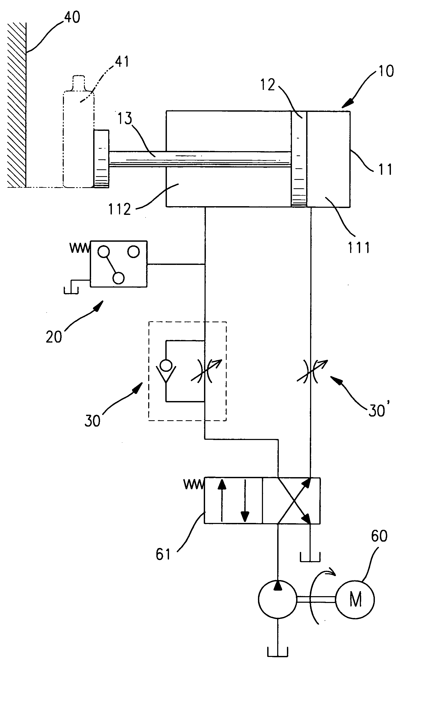
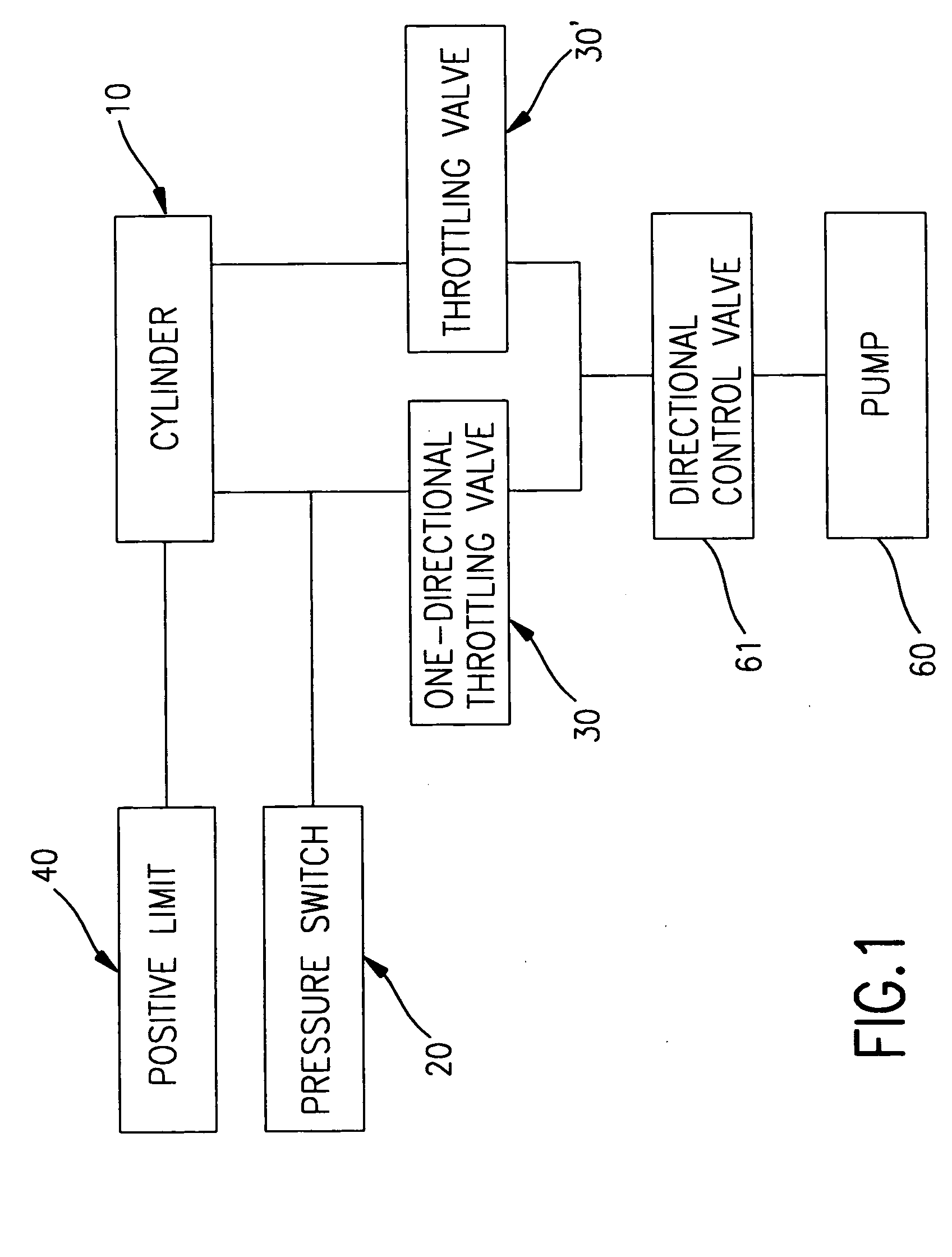
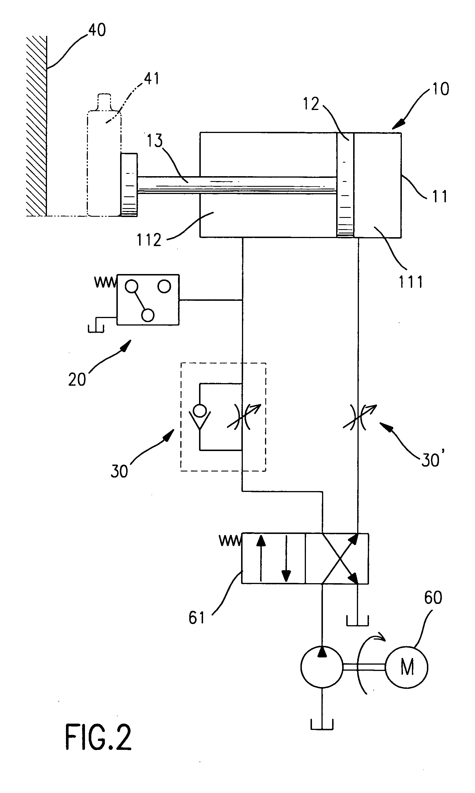
[0018] With reference to FIGS. 1 and 2, a cylinder apparatus with a capability of detecting piston position comprises a cylinder (10), pressure switches (20), throttling valves (30, 30′) and a positive limit (40). The cylinder apparatus can be used in a hydraulic system or a pneumatic system. A double-acting cylinder with a piston rod used in a hydraulic system is described, but a person skilled in the art will recognize that a single-acting cylinder or a double-acting cylinder with two opposite piston rods can be used.

[0019] The cylinder (10) is connected to a pumping device (not numbered) of the hydraulic system. The pumping device has a pump (60), pipes (not numbered) and directional control valves (61). The pump (60) is electrically connected to a controlling host (not shown) and pumps hydraulic fluid into the cylinder (10) via the pipes.

[0020] The cylinder (10) includes a closed tubular housing (11), a piston (12) and an actuating device (not numbered). A complex hydraulic sy...


PUM


Abstract

A cylinder apparatus with a capability of detecting a piston position includes a cylinder, a throttling valve, a positive limit and a pressure switch. A piston is movably mounted in the cylinder. A piston rod with an outside end protruding out of the cylinder is attached to the piston and adapted to push an object. The cylinder is connected to a pump with pipes. The throttling valve and the pressure switch are connected to the pipes, and the pressure switch is installed between the cylinder and the throttling valve. Consequently, when the pump starts pumping, the piston rod pushes the object to abut the positive limit. The stopped movement of the piston rod will change the pressure in the cylinder that triggers the pressure switch to send a signal to a controlling host to stop the pump.

Description

BACKGROUND OF THE INVENTION [0001] 1. Field of the Invention [0002] The present invention relates to a cylinder apparatus, and more particularly to a hydraulic or pneumatic system cylinder apparatus with a capability of detecting a piston position in a cylinder of the cylinder apparatus. [0003] 2. Description of Related Art [0004] In most hydraulic and pneumatic powered devices, cylinder apparatuses are the basic actuating elements. With reference to FIG. 4, a conventional cylinder apparatus with a capability of detecting a piston position includes a cylinder (50), reed switches (54) and permanent magnets (521). The cylinder (50) generally includes a closed tubular housing (51), a piston (52) and a piston rod (53). Since operation of the cylinder (50) is conventional, no description of the cylinder (50) operation is provided. [0005] The conventional method of detecting the piston (52) position in a cylinder (50) uses the permanent magnets (521) and reed switches (54). The permanent ...

Claims


Application Information

Patent Timeline
IPC IPC(8): A47B81/00A47B97/00F15B11/042F15B11/044F15B15/28
CPCF15B11/042F15B11/044F15B15/2838F15B2211/20538F15B2211/30525F15B2211/40515F15B2211/75F15B2211/41527F15B2211/455F15B2211/46F15B2211/473F15B2211/6313F15B2211/7053F15B2211/40584
Inventor CHUANG, YUN-CHING
Owner KSP TECH CORP
Learn More