
Mobile device battery charger mounting unit

a mobile device and charging unit technology, applied in the direction of coupling device details, coupling device connection, electric discharge lamps, etc., can solve the problems of unsafe access, difficult to reach, existing arrangement for charging a battery in a moving vehicle, etc., and achieve the effect of safe and convenient manner

Inactive Publication Date: 2005-07-07
NEXTEL
View PDF26 Cites 0 Cited by
  • Summary
  • Abstract
  • Description
  • Claims
  • Application Information

AI Technical Summary

Benefits of technology

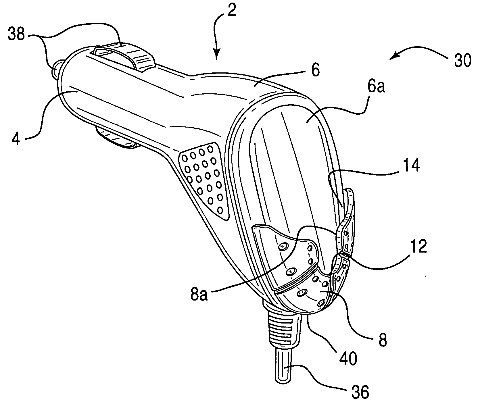
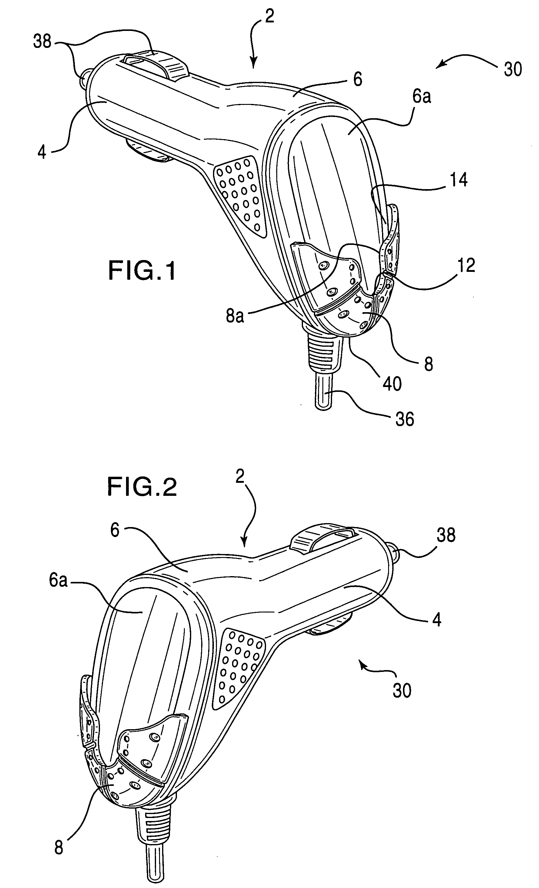
[0007] The present invention relates to a vehicular battery charger mounting unit for mounting a mobile communication device, such as a cellular telephone, having complementary features for such mounting while the battery is charging. Among other things, the vehicular battery charger mounting unit allows a driver or other user in the vehicle to access a cellular telephone, while it is charging, in a more safe and convenient manner.
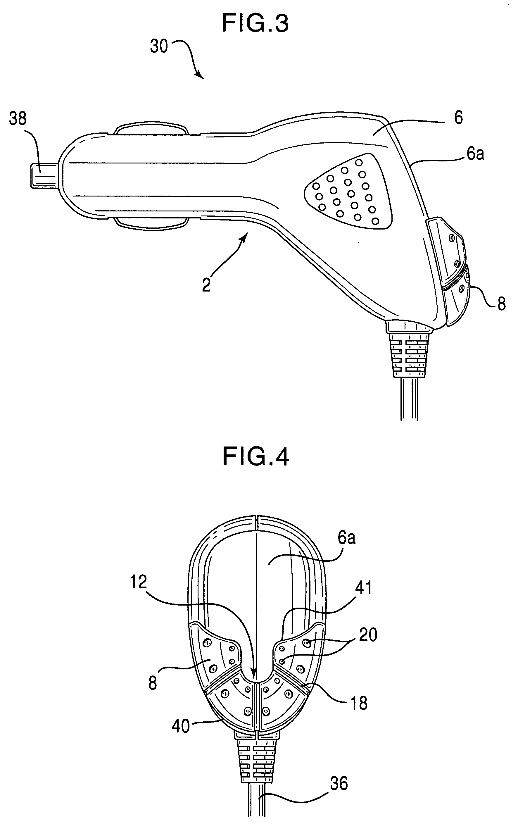
[0008] The vehicular battery charger for mounting a mobile communication device includes a charging member having a charging end and a mounting end. The charging end is connected to a power supply that charges the battery. The mounting end of the charging member has a mounting unit secured thereto. The mounting end can also have a charging cord, one end of which is connected to the battery and through which power is supplied to the battery or telephone. In one embodiment of the present invention, the mounting unit can have an arcuate surface extending toward the vehicle passenger compartment. The mounting unit also has a notched portion that acts as a holster or cradle for an attachment piece of the cellular telephone. The attachment piece connects the cellular telephone to the mounting unit. The notched portion of the mounting unit can be a U-shaped notch that facilitates the connection of the attachment piece.
[0010] In an embodiment of the present invention, a system of mounting a cellular telephone onto a vehicular battery charger includes a mounting unit at one end of the charger. The mounting unit includes a notched portion for receiving the detachable attachment piece. The attachment piece can optionally be snap-fit or otherwise detachably attached to the cellular telephone, to secure the piece onto the cellular telephone. The detachable attachment piece can be made from a resin material and includes a fastening member and a supporting member. In operation, once the detachable attachment piece is secured to the cellular telephone, the telephone can be docked into the notched portion of the mounting unit, thereby removably attaching the cellular telephone to the mounting unit.
[0013] An additional feature of the present invention is that the mounting unit serves to physically protect the cellular telephone so that when a passenger or driver enters the vehicle, neither one has to move the telephone from the vehicle seats to comfortably sit down. Also, as a result of the present invention, the vehicle occupants are is less likely to inadvertently sit or step on the telephone, possibly causing damage to the telephone.

Problems solved by technology

However, the existing arrangement for charging a battery in a vehicle, especially a moving vehicle if the telephone is also to be used, can be hazardous.
Specifically, the vehicular battery charging cord of existing chargers is long enough so that an individual can talk on the telephone while it is charging, but the charging cord is also long enough so that it can slide to different areas of the vehicle passenger compartment and not be accessible to the driver, or other vehicle occupants who seek to make or answer a call.
The cellular telephone can also be on the driver's floor, for example, under the brake pedal, or on the floor in front the passenger's seat, where it is difficult to reach when the vehicle is stationary and unsafe to reach when the vehicle is in motion.
The cellular telephone in such an arrangement creates a hazard inside the vehicle passenger compartment when the vehicle is in motion.
In particular, a hazard exists when the telephone rings, and the driver naturally has the urge to answer the telephone and must search for it in the vehicle passenger compartment because the telephone has moved away from the driver's immediate view.
The free movement of the cellular telephone in the vehicle passenger compartment can also result in physical damage to the telephone.

Method used


Image

  • Mobile device battery charger mounting unit
  • Mobile device battery charger mounting unit
  • Mobile device battery charger mounting unit

Examples


Embodiment Construction

[0021] The present invention is directed to a vehicular battery charger for charging a mobile communication device battery, such as a cellular telephone battery in an automobile. The vehicular battery charger of the present invention can be used to mount the cellular telephone thereon, so as to prevent the telephone, while charging, from being tossed about the vehicle passenger compartment when the vehicle is in motion. Further, the present invention prevents the charging cellular telephone from being misplaced in the vehicle even while the vehicle is parked. The stabilization of the cellular telephone acts as a safety and convenience feature, in that, while the cellular telephone is charging, it is readily visible and easily accessible, primarily to the driver, but also to passengers.

[0022] As shown in the perspective views of FIGS. 1 and 2 and also FIGS. 3 and 4, a vehicular battery charger 30 for mounting a mobile communication device, such as a cellular telephone, includes a ch...


PUM


Abstract

Cellular telephone mounting unit for a vehicular battery charger that supports and retains a cellular telephone onto a vehicle battery charger while the cellular telephone battery is charging. One variation of the mounting unit includes a semi-circular member having an arcuate surface, and a curved perimeter. The member including a notched portion formed in the arcuate surface so that a detachable attachment on the cellular telephone can be docked therein. The detachable attachment piece includes a supporting member and a fastening member. The fastening member including a head and a body rotatably connected thereto to allow the cellular telephone to pivot in the mounting unit.

Description

BACKGROUND OF THE INVENTION [0001] 1. Field of the Invention [0002] This invention relates to a cellular telephone mounting unit and complementary features for a telephone. More specifically, the present invention relates to a cellular telephone mounting unit for a vehicular battery charger so that the telephone is readily accessible to a driver or other user. [0003] 2. Description of the Related Art [0004] Cellular telephone use has grown tremendously in a short period of time. The cellular telephone has a significant usage outside of the home or business where traditional landline telephones still predominate. As a result, a significant percentage of cellular telephones are used in and around automobiles and other vehicles. Consistent use or even extended non-use of the cellular telephone naturally drains the cellular telephone battery. Thus, charging the battery can be necessary at any time, especially in the vehicle. However, the existing arrangement for charging a battery in a ...

Claims


Application Information

Patent Timeline
Patent Type & Authority Applications(United States)
IPC IPC(8): H01R31/06H01R33/945
CPCH01R31/065H01R2201/26H01R33/945H01R2201/16
Inventor RIVERA, WALTER
Owner NEXTEL
Learn More