Heat transfer member and method for manufacturing same

a technology of heat transfer member and heat transfer member, which is applied in the direction of indirect heat exchanger, laminated elements, light and heating apparatus, etc., can solve the problems of warping of a part or the entire heat transfer member, deformation, and ineffective heat exchange, and achieve the effect of reliable heat exchang

Inactive Publication Date: 2005-07-14
XENESYS
View PDF6 Cites 2 Cited by
  • Summary
  • Abstract
  • Description
  • Claims
  • Application Information

AI Technical Summary

Benefits of technology

[0008] An object of the present invention, which was made to solve the above-mentioned problems, is therefore to provide a heat transfer member in which prescribed press-formed portions are formed in addition to a pattern of irregularity serving as the heat transfer face so as to prevent abnormal deformation and maintain a proper distance between the adjacent heat transfer members, thus making a reliable heat exchange, on the one hand, and a method for manufacturing such a heat transfer member, on the other hand.

Problems solved by technology

The conventional heat transfer member having the above-described structure causes a problem of making deformation of the heat transfer member thorough pressure of fluids to bring the adjacent heat transfer members into contact with each other, when the distance between the adjacent heat transfer members is extremely small and there exists a large pressure difference between a high pressure fluid and a low pressure fluid, which flow along the opposite surfaces of the heat transfer member.
Such a problem leads to improper change in distance between the adjacent heat transfer members and damage to the heat transfer face, thus causing possibility that effective heat exchange may not be performed.
A remarkable residual distortion exists in the pressed portion and the non-pressed portion of the heat transfer member after completion of the press formation, thus causing problems of warp of a part or entirety of the heat transfer member and deformation thereof.

Method used


Image

  • Heat transfer member and method for manufacturing same
  • Heat transfer member and method for manufacturing same
  • Heat transfer member and method for manufacturing same

Examples


Embodiment Construction

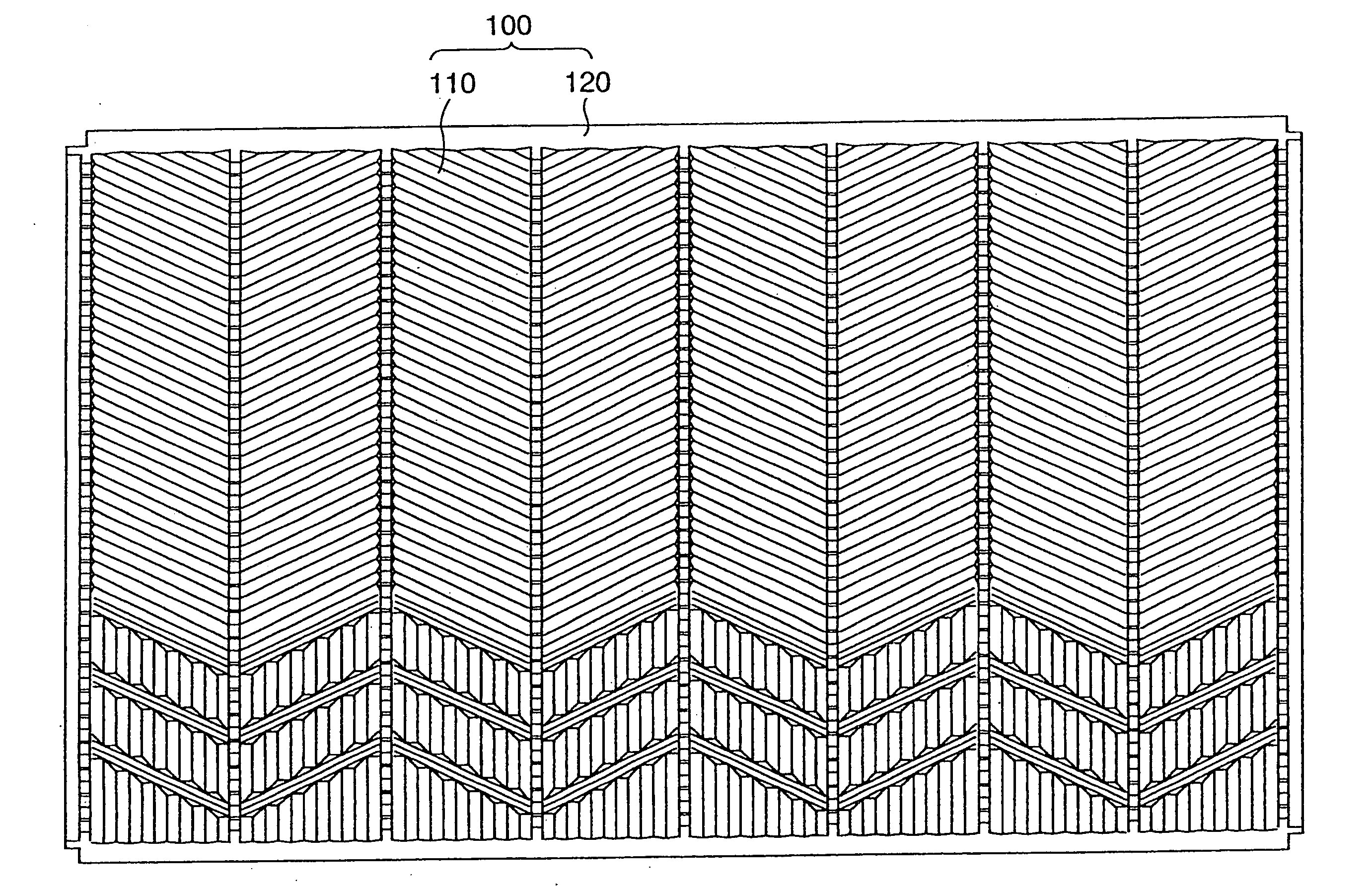
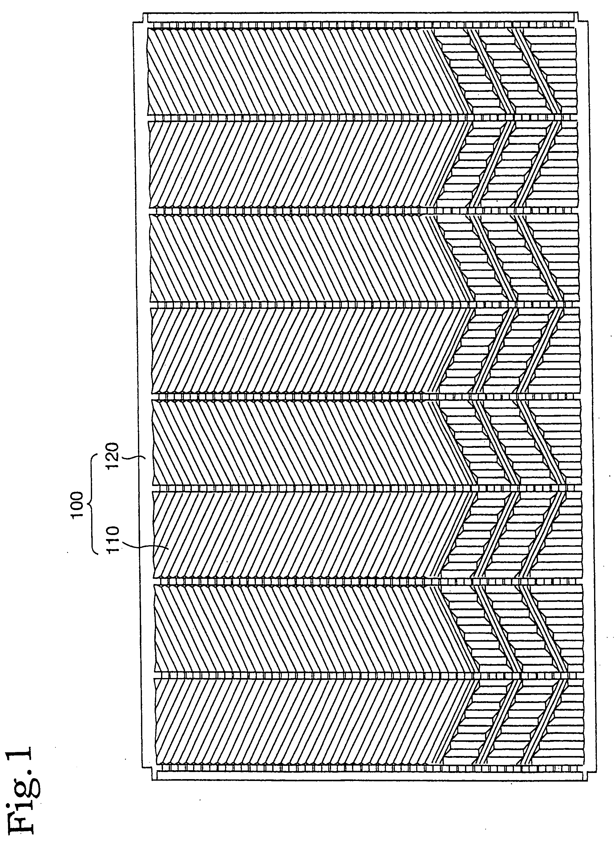
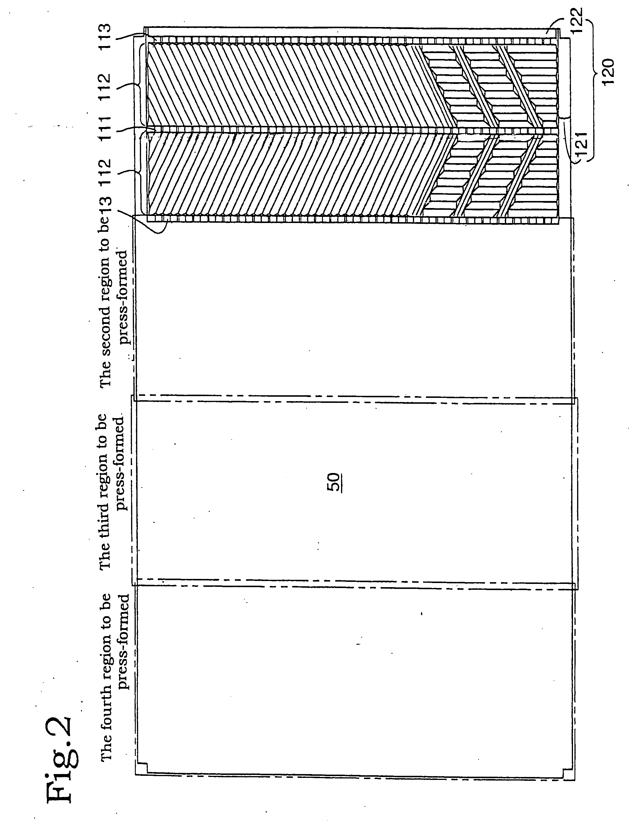
[0039] Now, the embodiment of the present invention will be described in detail below with reference to FIGS. 1 to 9. FIG. 1 is a front view illustrating a heat transfer member in accordance with the embodiment of the present invention; FIG. 2 is a descriptive view illustrating a state in which the press-forming step is being carried out in accordance with the embodiment of the present invention; FIG. 3 is a descriptive view of a press-forming operation, which is applied to one end of the material to be worked in accordance with the embodiment of the method of the present invention for manufacturing the heat transfer member; FIG. 4 is a descriptive view of a press-forming operation, which is applied to the intermediate portion of the material to be worked in accordance with the embodiment of the method of the present invention for manufacturing the heat transfer member; FIG. 5 is a descriptive view of a press-forming operation, which is applied to the other end of the material to be...


PUM

PropertyMeasurementUnit
widthaaaaaaaaaa
heat transfer coefficientaaaaaaaaaa
temperatureaaaaaaaaaa

Abstract

A heat transfer member for a heat exchanger, is press-formed of a metallic thin sheet material into a prescribed shape by means of molds of a press forming device so that the heat transfer member has on at least one portion thereof a heat transfer face having opposite surfaces, which are to be brought into contact with heat exchange fluids, respectively. The heat transfer face comprises at least one set of irregularity patterns arranged in a row. Each of the at least one set of irregularity pattern units comprises (i) a central pattern portion having a plurality of recesses or projections provided with a prescribed pitch, (ii) a pair of heat exchanging irregularity pattern portions provided on opposite sides of the central pattern portion so as to be symmetrical with respect to the central pattern portion and (iii) at least one boundary pattern portion provided on at least one of respective outer sides of the pair of heat exchanging irregularity pattern portions so as to be adjacent to the respective outer sides thereof. The boundary pattern portion has a prescribed width and a plurality of recesses or projections provided with a same pitch as the plurality of recesses or projections of the central pattern portion so as to be in parallel therewith.

Description

BACKGROUND OF THE INVENTION [0001] 1. Field of the Invention [0002] The present invention relates a heat transfer member for a heat exchanger, which is obtained by press-forming material to be worked, on the one hand, and a method for manufacturing such a heat transfer member, on the other hand, and especially to the heat transfer member in which a plurality of press-formed portions having a prescribed shape are arranged, on the one hand, and the method for manufacturing same, by which the press-formed portions can be formed on the material to be worked in an appropriate arrangement. [0003] 2. Description of the Related Art [0004] If there is a wish that heat transfer coefficient is increased to enhance heat exchange effectiveness, utilizing a heat exchanger by which heat exchange is made between a high temperature fluid and a low temperature fluid, a plate-type exchanger has conventionally been used widely. The plate-type exchanger has a structure in which a plurality of heat trans...

Claims


Application Information

Patent Timeline
Patent Type & Authority Applications(United States)
IPC IPC(8): B21D53/04F28D9/00F28F3/04
CPCB21D53/04Y10T29/4935F28F3/04F28D9/0037
Inventor MATSUZAKI, TOYOAKI
Owner XENESYS
Why Eureka
Try Eureka