Positive pipe interlock

a positive and interlocking technology, applied in the direction of combustion process, lighting and heating apparatus, combustion treatment, etc., can solve the problems of not holding the pipe in place, time-consuming and expensive, and the cost of an additional piece and the associated assembly time,

Inactive Publication Date: 2005-07-21
FLEXMASTER CANADA
View PDF11 Cites 6 Cited by
  • Summary
  • Abstract
  • Description
  • Claims
  • Application Information

AI Technical Summary

Benefits of technology

[0009] The present invention features a system and method for positively joining two pipes, such as stovepipe or conduit. A first pipe is made with an indentation about the perimeter of one end, into which a second pipe may be snugly fitted. The second pipe has one or more protrusions about the perimeter near the end to be inserted into the first pipe. The protrusions are shaped so as to allow passage past the indentation in the first pipe during insertion of the second pipe, while resisting disassembly by withdrawing the second pipe. In one embodiment, the protrusions are wedge shaped. In another embodiment, the protrusions are hemispherical. The principles of the present invention are applicable to multi-walled pipes as well.

Problems solved by technology

This requires drilling or punching, and manually installing screws, which can be both time consuming and expensive.
Moreover, such a method does nothing to hold the pipe in place while it is being installed.
Again, this requires the expense of an additional piece and the associated assembly time, as well as doing nothing to hold the pipe in place during installation.
This gives a positive lock during installation, but may prove difficult to install when joining pipes that must be joined at a set orientation (such as an elbow) because the desired angle at which the pipes lock together may or may not be the angle desired for the particular installation.
Moreover, twisting the inner pipe to cause locking may be difficult because of friction between the inner and outer pipes.

Method used


Image

  • Positive pipe interlock
  • Positive pipe interlock
  • Positive pipe interlock

Examples


Embodiment Construction

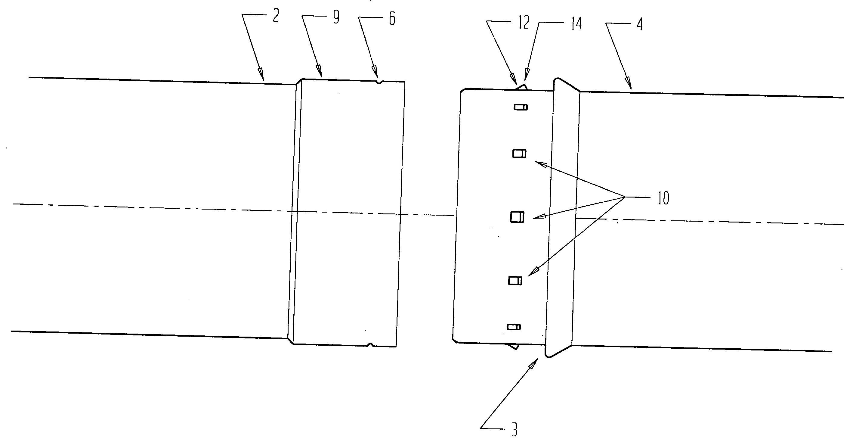
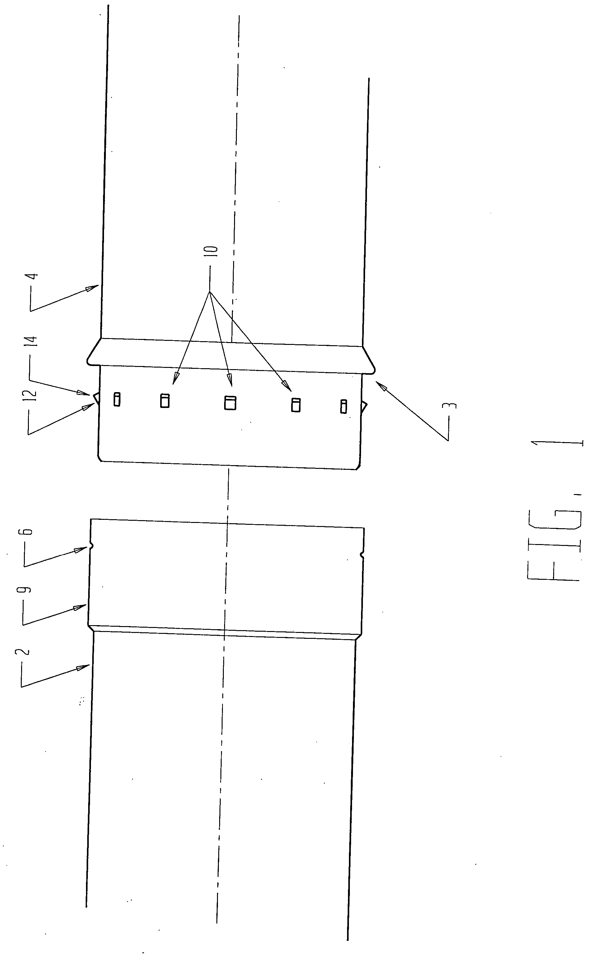
[0014] The present invention provides a method and system for positively joining two pipes. No additional parts are required to effectuate the positive interlock, which may, when the pipes are made of a suitable deformable elastically material such as sheet metal, be disassembled.

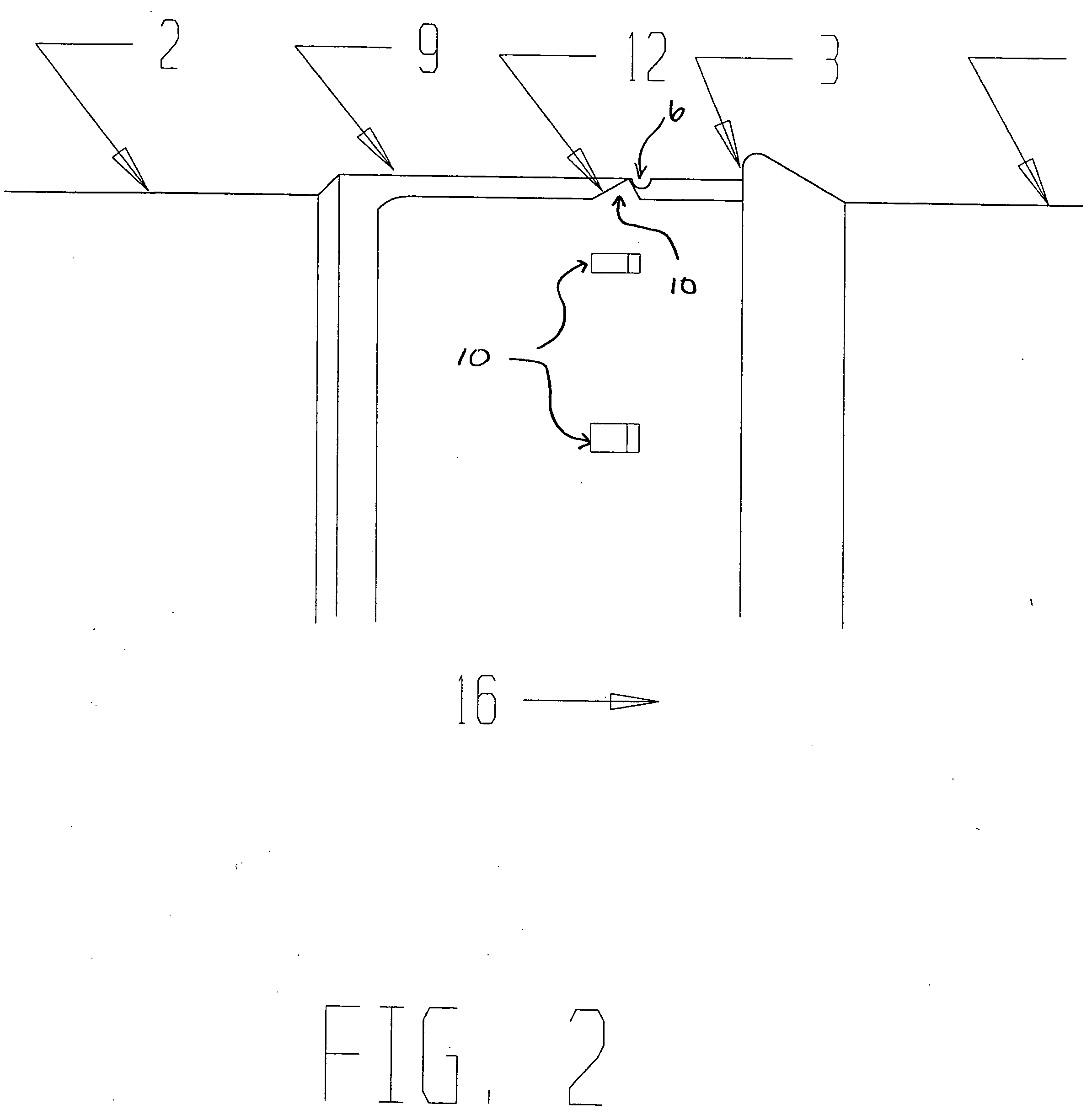
[0015] Referring to FIG. 1, two pipes made according to the principles of the present invention are shown. A first pipe 2 has one end expanded so it slides over the protrusion 10 of the second pipe 4 and has an indentation 6 about the perimeter. This indentation, in the case of pipe made from sheet metal, may easily be made in a rolling operation.

[0016] Spaced about the circumference of the end of the second pipe 4 are a number of protrusions 10 located so that, when the expanded size portion 9 of the first pipe 2 is sliding over the end of the second pipe 4, the protrusions 10 may slide tightly past the indentation 6. In the present example, the protrusions 10 are wedge shaped, with the thin edge of the ...


PUM

PropertyMeasurementUnit
perimeteraaaaaaaaaa
distanceaaaaaaaaaa
thickaaaaaaaaaa

Abstract

A system and method is taught of positively joining to pipes, such as stovepipe or conduit. A first pipe is made with an indentation about the perimeter of one end, into which a second pipe is fitted snugly. The second pipe has a plurality of protrusions about the perimeter near the end to be inserted into the first pipe. The protrusions are shaped so as to allow passage past the indentation in the first pipe during insertion of the second pipe, while resisting disassembly by withdrawing the second pipe.

Description

TECHNICAL FIELD [0001] The present invention relates to pipe interconnections and more particularly, to a method and system of interconnecting pipe and to a pipe manufactured with a novel interconnection system. BACKGROUND INFORMATION [0002] Thin-walled pipe and conduit is used for a variety of purposes. For example, thin-walled metal pipe is used as chimney pipe for wood stoves. Round and rectangular thin-walled conduit is used in distributing hot air in a heating system or air conditioning system. Double walled pipe may be used to vent a furnace. [0003] Depending upon the application, such pipes may be made from stainless or galvanized sheet metal steel, or may be made from a flexible plastic material. The pipes may be single walled or multiple walled, multiple walled pipes typically being used to provide a thermal insulating layer between the pipe contents and the outer wall of the pipe. [0004] Such pipes typically come in fixed lengths, and are expanded in diameter at one end so...

Claims


Application Information

Patent Timeline
Patent Type & Authority Applications(United States)
IPC IPC(8): F16L21/08F16L37/26
CPCF23J2211/101F23J2213/202F16L37/025Y10T29/4987F16L37/565Y10T29/49876Y10T29/49863F16L37/098
Inventor ISENDAM, JULESBRUNT, MICHAELGOODERHAM, WAYNE
Owner FLEXMASTER CANADA
Why Eureka
Try Eureka