Methods and apparatus for facilitating security and tamper control

a technology for facilitating security and tampering, applied in the direction of identification means, carpet fasteners, instruments, etc., can solve the problems of head not being removed from the body without damaging the device, the head, the wire, the head, etc., and achieve the effect of reducing the incidents of pilferag

Active Publication Date: 2005-07-21
CHING HENRY KONG SUN
View PDF22 Cites 2 Cited by
  • Summary
  • Abstract
  • Description
  • Claims
  • Application Information

AI Technical Summary

Benefits of technology

[0007] In accordance with one more aspects of the present invention, an apparatus is provided that reduce the incidents of pilferage of sensitive items. The apparatus may include a body made of plastic, metal or metal alloy, or combination of both, a wire coupled at one end to the body, made of copper or any other metal, plastic or combination of both, and an umbrella-like structure made of plastic, metal, metal alloy or combination of both disposed at another end of the wire. The umbrella-like structure (or head) may lock into the body. Notably, the head may not be removed from the body without damaging the device. By way of example, in use the head and wire may be passed through the loops of a piece of luggage such as a zipper (or any other aperture that can be used to seal or enclose an item of interest). Next, the head is inserted into the body and is locked in place. Thus, the loops of the zipper may not be separated because the body and the wire of the device prevents their separation. Notably, the insertion of the head into the body does not result in a rigid, non-movable relationship between the head and the body; rather, the head is locked in the body but may be moved slightly in and out when properly engaged.

Problems solved by technology

Notably, the head may not be removed from the body without damaging the device.
Thus, the loops of the zipper may not be separated because the body and the wire of the device prevents their separation.
In order to breach the device, an unauthorized person would have to permanently damage the body, the head, the wire, or the loops of the luggage.
At first blush, this would appear to conceal that tampering had occurred; however, proper inspection would clearly show that unauthorized access took place.

Method used


Image

  • Methods and apparatus for facilitating security and tamper control
  • Methods and apparatus for facilitating security and tamper control
  • Methods and apparatus for facilitating security and tamper control

Examples


Embodiment Construction

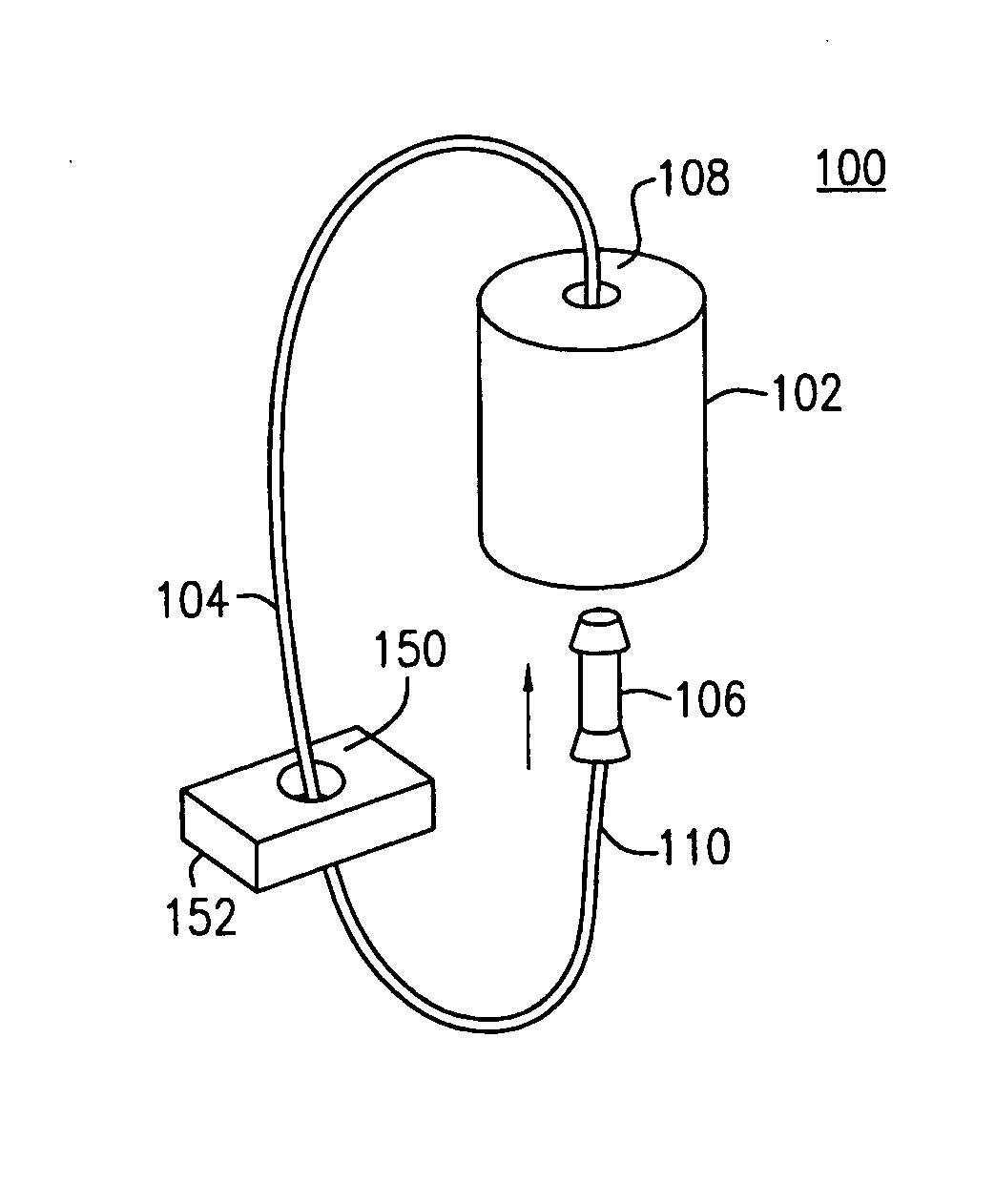
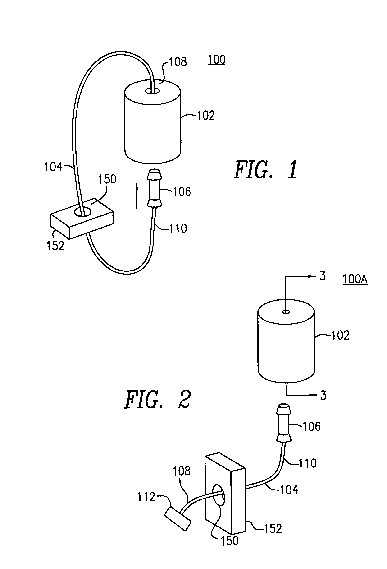
[0033] Reference is now made to the drawings, wherein like numerals indicate like elements. FIG. 1 is a perspective view of a security device 100 in accordance with one or more aspects of the present invention. The security device 100 includes a body 102, a wire 104 and a head 106. In this embodiment of the invention, the wire 104 is coupled at one end 108 to the body 102. Another end 110 of the wire 104 is coupled to the head 106. Preferably, the body 102 and the head 106 are formed from a suitable plastic material, metal, metal alloy or combination of plastic and metal, and the ends 108, 110 of the wire 104 are preferably embedded into the body 102 and the head 106, respectively, during the manufacturing process.

[0034] The body 102 is preferably of a generally cylindrical configuration, although those skilled in the art will appreciate that the body 102 may take on any desirable shape without departing from the spirit and scope of the invention. In use, the head 106 preferably pa...


PUM


Abstract

An apparatus includes: a head; a metal wire having a first end coupled to the head and a second end coupled to a stop member; and a body having a cavity for receiving and locking the head such that when the head is locked in the cavity it cannot be removed without destroying the apparatus, wherein the head and the metal wire are operable to pass through one or more apertures of an object and the head is operable to lock in the cavity such that the body and the stop member retain the wire in engagement with the aperture and maintain the apparatus locked to the object.

Description

CROSS REFERENCE TO RELATED APPLICATIONS [0001] This application is based on and claims the benefit of U.S. Provisional Patent Application No. 60 / 568,619, filed May 6, 2004; and U.S. Provisional Patent Application No. 60 / 537,831, filed Jan. 21, 2004, the entire disclosures of which are hereby incorporated by reference.BACKGROUND OF THE INVENTION [0002] The present invention relates to an apparatus for facilitating security and tamper controls and, more particularly, to providing a device that will indicate whether one or more items have been tampered with in an unauthorized manner. [0003] The desire to eliminate tampering or other unauthorized access to information, services, goods, etc. is well known. Indeed, hundreds of years ago the use of locks, containers, personal guards, etc. were utilized in order to insure that only authorized individuals could gain access to valuable items. While it is often desirable to insure that unauthorized access is prevented, it may also be desirable...

Claims


Application Information

Patent Timeline
Patent Type & Authority Applications(United States)
IPC IPC(8): A41B1/00G09F3/03H01J1/02
CPCG09F3/0311G09F3/0352Y10T24/1498Y10S292/38G09F3/0364Y10T292/491Y10T292/48Y10T292/496Y10T292/50Y10T292/494Y10T292/516
Inventor CHING, HENRY KONG SUN
Owner CHING HENRY KONG SUN
Why Eureka
Try Eureka