Eureka AIR delivers breakthrough ideas for toughest innovation challenges, trusted by R&D personnel around the world.

Gradient coil and method for construction

Active Publication Date: 2005-07-21
GE MEDICAL SYST GLOBAL TECH CO LLC
View PDF14 Cites 4 Cited by
  • Summary
  • Abstract
  • Description
  • Claims
  • Application Information

AI Technical Summary

Benefits of technology

[0005] The disclosed apparatus relates to a gradient coil assembly for a magnetic resonance imaging system. The gradient coil assembly comprises: at least two coils. The coils comprise: at least one conductor mechanically bonded via a nonconducting substrate. The bonding surface of the at least one conductor has been subjected to a surface treatment to improve the mechanical bonding properties of the bonding surface.
[0006] The disclosed apparatus also relates to a magnetic imaging system. The magnetic imaging system comprises: a system controller; a gradient amplifier unit in operable communication with the system controller; a magnetic assembly in operable communication with the gradient amplifier. The magnetic assembly comprises: a gradient coil assembly comprising at least two coils. The coils comprise: at least one conductor mechanically via a nonconducting substrate. A bonding surface of the at least one conductor has been subjected to a surface treatment to improve the mechanical bonding properties of the bonding surface.

Problems solved by technology

This increased force load is placing ever higher demands on the structural integrity of the gradient coil.

Method used


Image

  • Gradient coil and method for construction
  • Gradient coil and method for construction
  • Gradient coil and method for construction

Examples


Embodiment Construction

[0012] A detailed description of several embodiments of the disclosed apparatus and method are presented herein by way of exemplification and not limitation with reference to FIGS. 1 through 3. Identical reference numerals represent identical components in the various views.

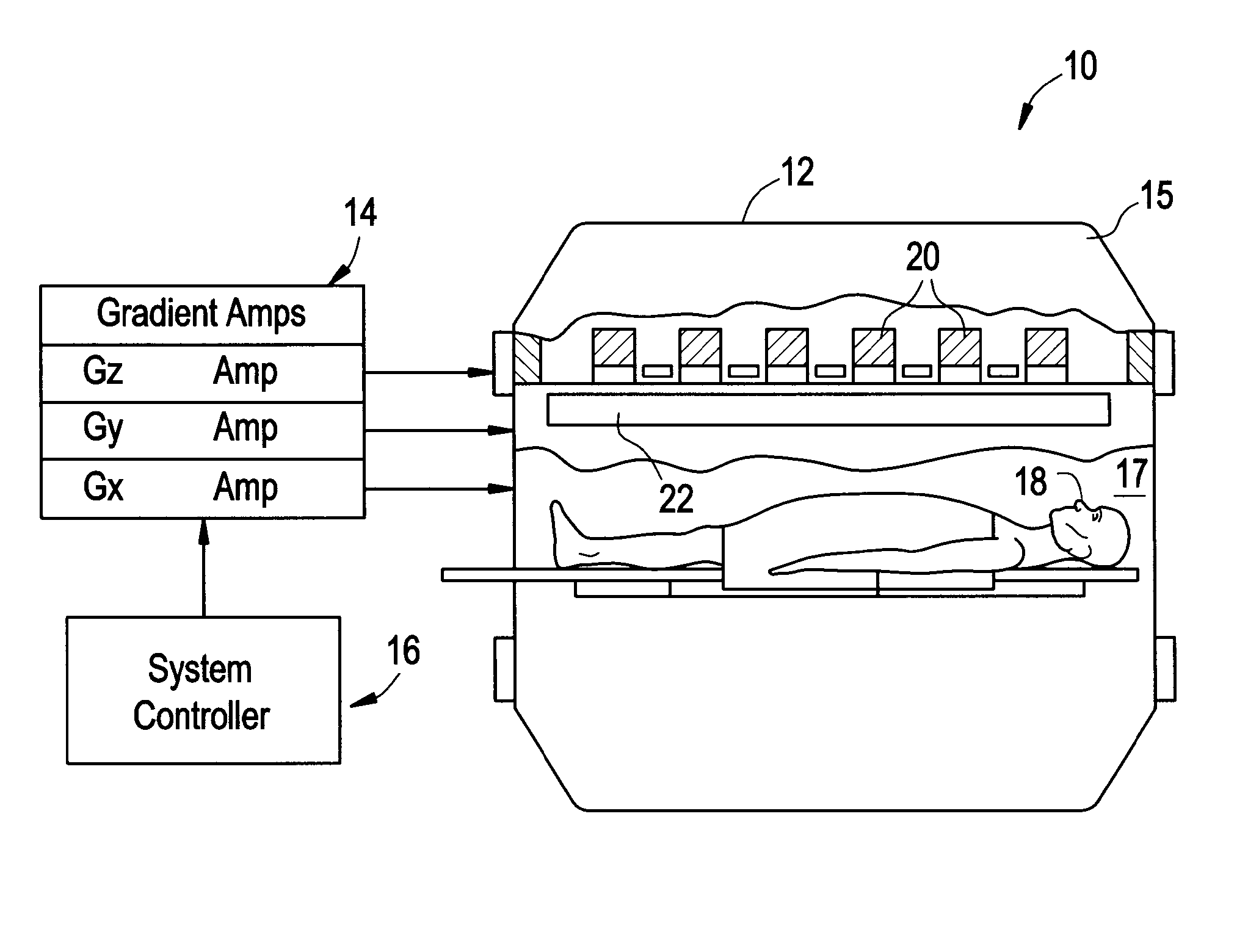
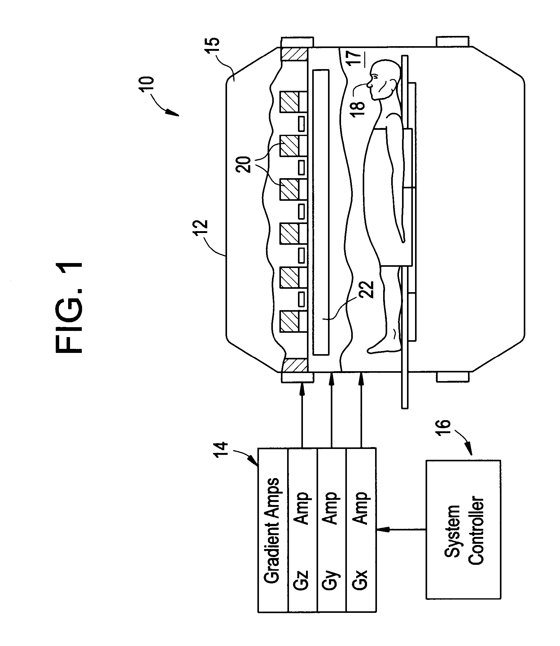
[0013] Referring to FIG. 1, an exemplary MRI system 10 is provided for generating images of a person 18. MRI system 10 may comprise a magnetic assembly 12, a gradient amplifier unit 14, and a system controller 16.

[0014] Magnetic assembly 12 is provided to generate magnetic fields that will be propagated to person 18. Assembly 12 may comprise a housing 15 defining a chamber 17 for receiving person 18. Assembly 12 may further comprise polarizing magnets 20, and a gradient coil assembly 22 having a plurality of coils. Gradient coil assembly 22 generate magnetic fields along a predetermined axes in response to signals received from the gradient amplifier unit 14.

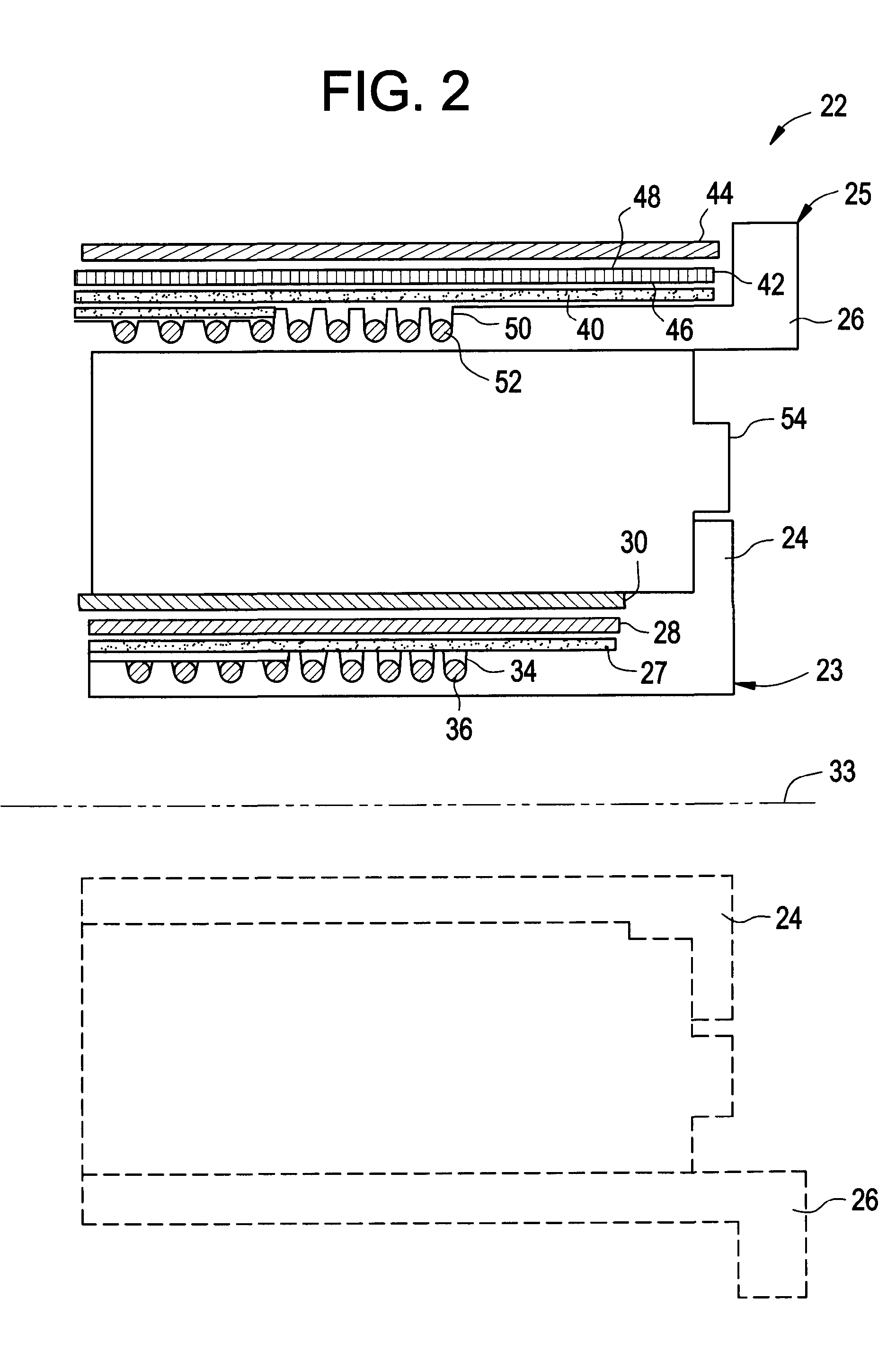
[0015] Referring to FIG. 2, an exemplary gradient co...


PUM


Abstract

The disclosed apparatus relates to a gradient coil assembly for a magnetic resonance imaging system. The gradient coil assembly comprises: at least two coils. The coils comprise: at least one conductor mechanically bonded via a nonconducting substrate. The bonding surface of the at least one conductor has been subjected to a surface treatment to improve the mechanical bonding properties of the bonding surface. The disclosed apparatus also relates to a magnetic imaging system. The magnetic imaging system comprises: a system controller; a gradient amplifier unit in operable communication with the system controller; a magnetic assembly in operable communication with the gradient amplifier. The magnetic assembly comprises: a gradient coil assembly comprising at least two coils. The coils comprise: at least one conductor mechanically bonded via a nonconducting substrate. A bonding surface of the at least one conductor has been subjected to a surface treatment to improve the mechanical bonding properties of the bonding surface. The disclosed method relates to assembling a gradient coil assembly. The method comprises: treating a bonding surface of at least one conductor; and bonding the at least one conductor to a nonconducting substrate.

Description

TECHNICAL FIELD [0001] The current disclosed method and apparatus relate to a magnetic resonance imaging (“MRI”) system. More specifically, the disclosed method and apparatus relate to a gradient coil used in an MRI system. BACKGROUND OF THE INVENTION [0002] MRI systems use gradient coils to generate magnetic field gradients along desired axes. Copper conductors in the gradient coils are usually held in place in the gradient coils by a mechanical bonding, often some type of nonconductive epoxy resin. Adjacent gradient coils are generally separated a predetermined distance. A gap formed between adjacent gradient coils may be filled with a nonconductive epoxy resin. [0003] The gradient coil carries current in the copper conductors, and must operate in a background field of an MRI magnet. The demands on the performance of the gradient coil have increased due to higher currents, higher background fields, and the need for lower acoustic noise. In particular, the peak operating current ha...

Claims


Application Information

Patent Timeline
IPC IPC(8): G01R33/385
CPCG01R33/3854
Inventor HAVENS, TIMOTHY JOHNSELLERS, MICHAELGREY, DELTON
Owner GE MEDICAL SYST GLOBAL TECH CO LLC
Why Eureka
Eureka Blog
Learn More