Zero-force pellicle mount and method for manufacturing the same

a technology of pellicle mounts and mounts, applied in the field of semiconductor lithography, can solve the problems of insufficient pellicle material use methods, deformation of all known polymers, and inability to meet the requirements of pellicle mountings,

Inactive Publication Date: 2005-07-21
INT SEMATECH
View PDF8 Cites 21 Cited by
  • Summary
  • Abstract
  • Description
  • Claims
  • Application Information

AI Technical Summary

Benefits of technology

[0010] The present invention provides a method and an apparatus for attaching a pellicle, such as a fused silica pellicle, to a reticle. According to one aspect of the invention, the method may provide a multi-support point pellicle holder for providing a substantially equal support force at each of the points. In some respects, the multi-support point pellicle holder may include six supports pins. Alternatively, the multi-support point pellicle holder may include eight support pins. The method also provides a multi-support point reticle holder for providing a substantially equal support force at each of the four points. In some respects, the multi-support point reticle holder may include four support pins. In some embodiments, an adhesive is added to the pellicle. In one embodiment, adhesive spots are placed on the pellicle, one adhesive spot over each of the support points on the multi-support point pellicle holder. Alternatively, a contiguous adhesive layer may be added to the pellicle frame. Due to the force from the application of the reticle to the pellicle, the adhesion bonds the reticle to the pellicle with substantially no distortion.

Problems solved by technology

The image is projected using a photomask which must be kept clean because any undesired particles on the surface may alter the image on the wafer and cause a defect.
For 157 nanometer wavelengths exposure, all known polymers degrade to such an extent that they are unusable as pellicle material.
The referenced shortcomings are not intended to be exhaustive, but rather are among many that tend to impair the effectiveness of previously known techniques concerning pellicle design; however, those mentioned here are sufficient to demonstrate that the methodologies appearing in the art have not been satisfactory and that a significant need exists for the techniques described and claimed in this disclosure.

Method used


Image

  • Zero-force pellicle mount and method for manufacturing the same
  • Zero-force pellicle mount and method for manufacturing the same
  • Zero-force pellicle mount and method for manufacturing the same

Examples


Embodiment Construction

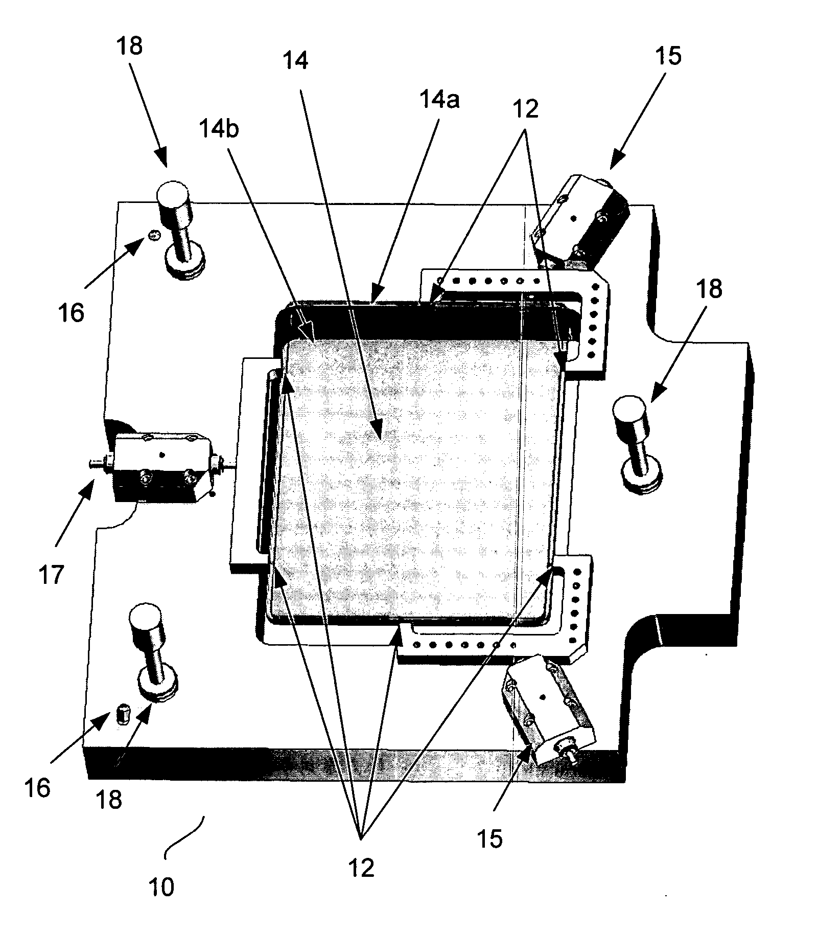
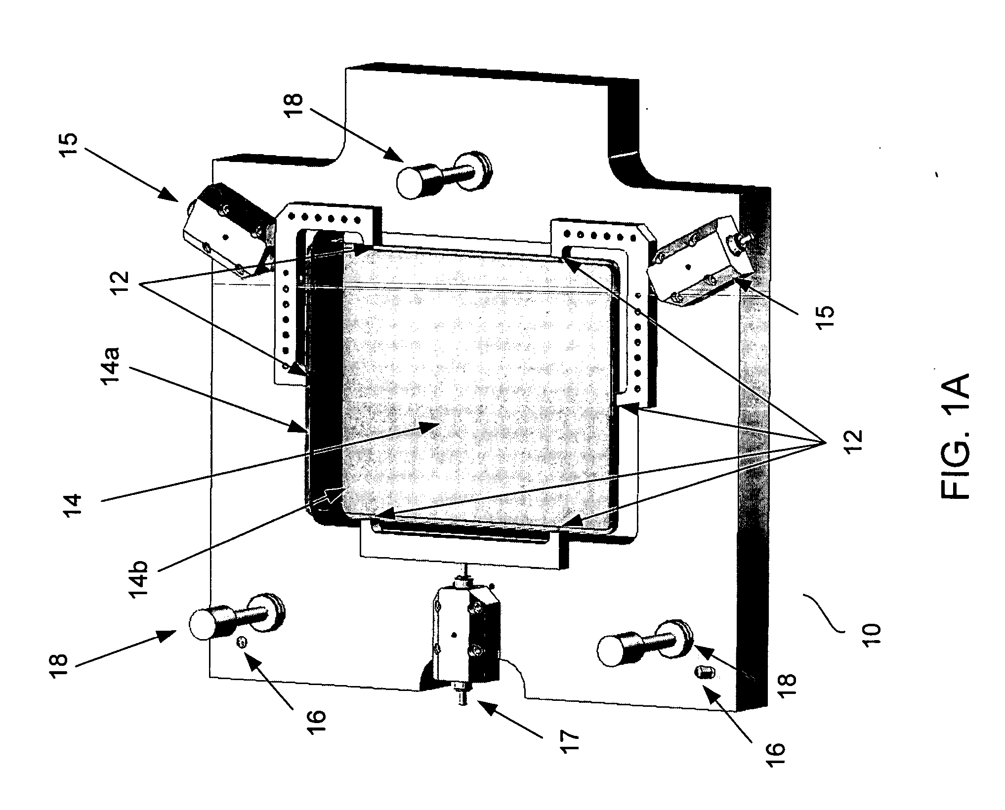
[0019] The present invention presents an improved mounting method of a fused silica pellicle to a reticle without introducing distortion to the pellicle. The invention also presents an apparatus including a multi-support point holder that supports the fused silica pellicle attached to a multi-support point holder that supports the reticle. The method and apparatus departs from the current practice of optical contacting since the current technique does not allow for any possible planarity difference between the reticle and the pellicle. Furthermore, optical contacting involves heat and pressure which tends to distort the pellicle.

[0020] In accordance to one embodiment of the invention, a fused silica pellicle may be supported by support pins of a pellicle holder that provides an even support to the entire surface of the pellicle such that the shape of the pellicle is not altered. Referring to FIG. 1A, a six-support point pellicle holder 10 supports a pellicle 14. Fused silica pellic...


PUM

PropertyMeasurementUnit
thicknessaaaaaaaaaa
thickaaaaaaaaaa
wavelengthsaaaaaaaaaa

Abstract

Methods and apparatuses for mounting a pellicle to a reticle is provided. A multi-support point pellicle holder supports a pellicle, such as a fused silica pellicle, and a multi-support point holder supports the reticle, where each point on the respective frame provides a substantially equal-force. An adhesive is added to the pellicle, where upon attaching the reticle pellicle, the weight of the reticle causes the adhesive spots to form a wider bonding layer, adhering the pellicle to the reticle. The adhesive layer is cured and a sealant is added in the spaces between the adhesive spots.

Description

[0001] This patent application claims priority to, and incorporates by reference in its entirety, U.S. Provisional Patent Application Ser. No. 60 / 525,499 filed on Nov. 26, 2003.BACKGROUND OF THE INVENTION [0002] 1. Field of the Invention [0003] This invention relates to the field of semiconductor lithography and more specifically to mounting a fused silica pellicle to a reticle. [0004] 2. Discussion of the Related Art [0005] In the production of semiconductor devices, there are a number of lithographic exposure steps in which an image is projected onto a photosensitive material coating on a semiconductor wafer. The image is projected using a photomask which must be kept clean because any undesired particles on the surface may alter the image on the wafer and cause a defect. [0006] A common method to achieve this goal has been the application of a protective membrane spaced apart from the mask by a few millimeters. At this offset, particles on the protective membrane will be out of f...

Claims


Application Information

Patent Timeline
Patent Type & Authority Applications(United States)
IPC IPC(8): G03B27/52G03F1/14
CPCG03F1/64
Inventor VAN PESKI, CHRISTIAN K.GRENVILLE, ANDREW
Owner INT SEMATECH
Why Eureka
Try Eureka