
Scan image correction device and method thereof

a correction device and scanner technology, applied in the field of scanner image correction device, can solve the problems of low-quality image generation and degrade readability, and achieve the effect of preventing black lines on the imag

Inactive Publication Date: 2005-07-21
SAMSUNG ELECTRONICS CO LTD
View PDF3 Cites 14 Cited by
  • Summary
  • Abstract
  • Description
  • Claims
  • Application Information

AI Technical Summary

Benefits of technology

[0014] The present general inventive concept provides a scan image correction device which determines the presence of an ESD occurring when the scan image generation device scans an image, to prevent black lines on the document, and a method thereof.
[0024] By the above process, a scan image correction device according to the present general inventive concept can determine the presence of the ESD occurring when the scan image generation device scans an image, to prevent black lines on the image.

Problems solved by technology

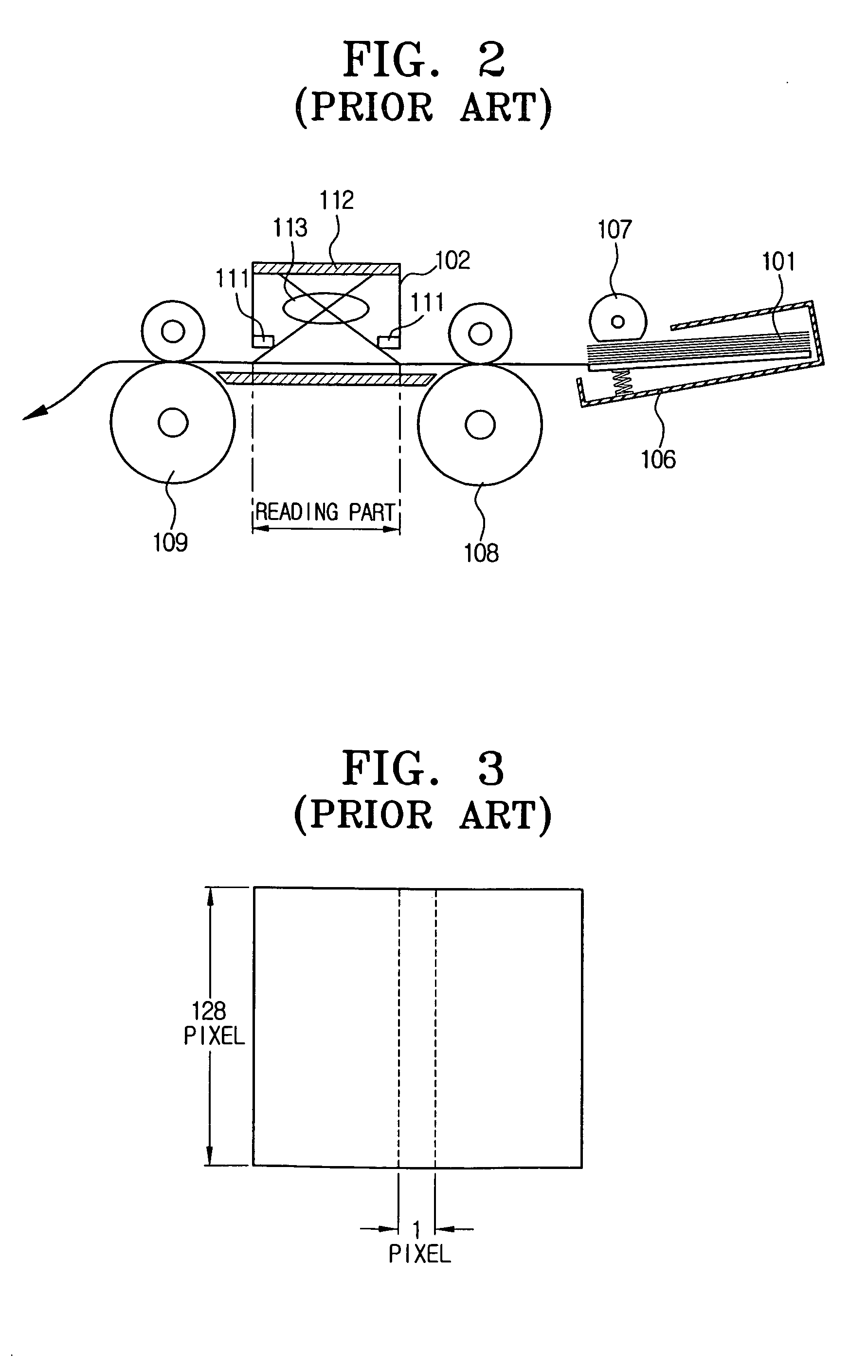
The black lines degrade readability and therefore, a low-quality image is generated.

Method used


Image

  • Scan image correction device and method thereof
  • Scan image correction device and method thereof
  • Scan image correction device and method thereof

Examples


Embodiment Construction

[0033] Reference will now be made in detail to the embodiments of the present general inventive concept, examples of which are illustrated in the accompanying drawings, wherein like reference numerals refer to the like elements throughout. The embodiments are described below in order to explain the present general inventive concept by referring to the figures.

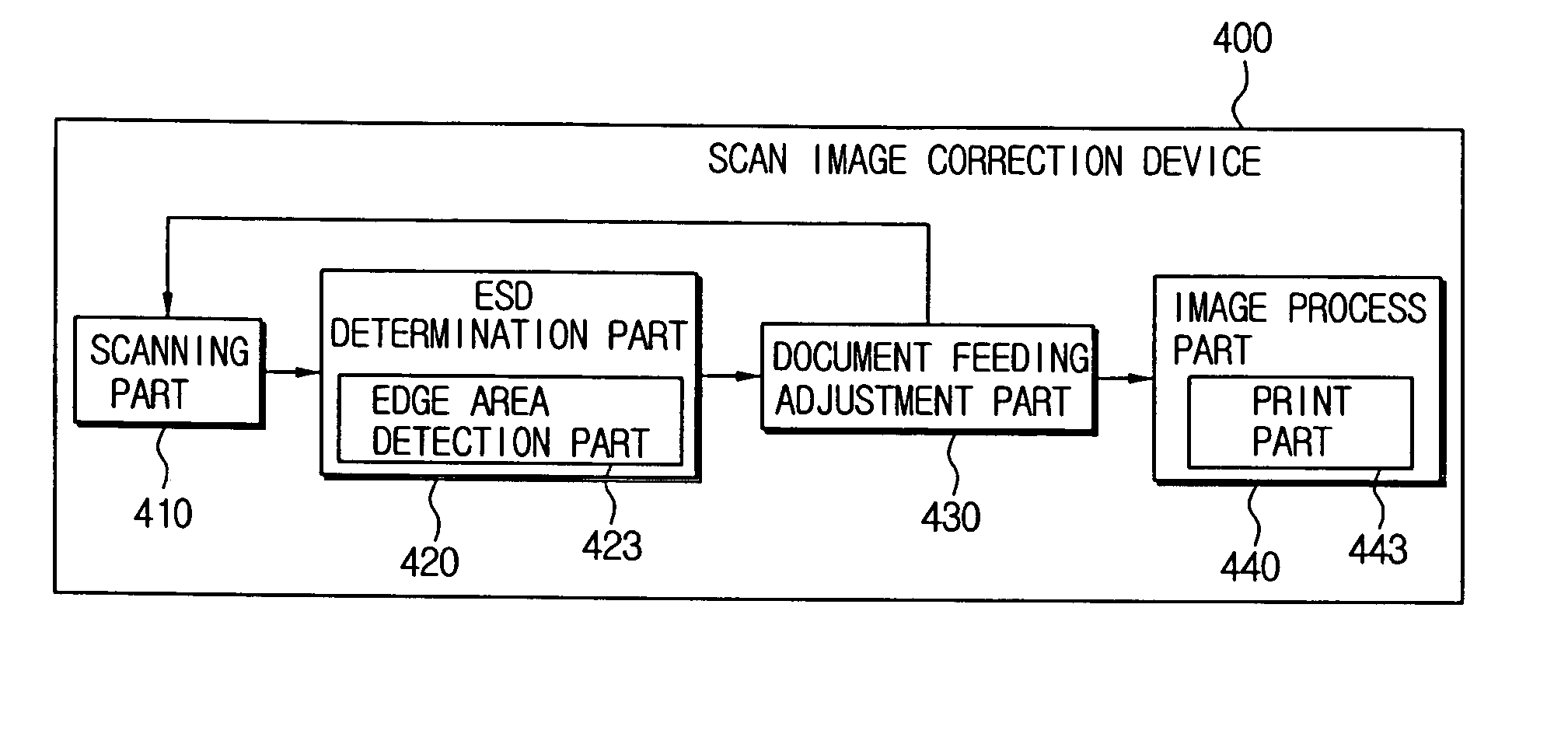
[0034]FIG. 4 is a block diagram illustrating a scan image correction device according to an embodiment of the present general inventive concept. The scan image correction device 400 comprises a scanning part 410, an ESD (electro static discharge) determination part 420, a document feeding adjustment part 430, and an image process part 440. The ESD determination part 420 can have an edge area detection part 423. The image process part 440 can have a print part 443.

[0035] The scanning part 410 scans an image of a document in a block unit. The scanning part 410 may have a charge coupled device (CCD) or a contact image sensor (CI...


PUM


Abstract

A scan image correction device includes a scanning part to scan an image of a document in a block unit, an electro static discharge (ESD) determination part to determine a presence of an external ESD while the scanning part scans the image, a document feeding adjustment part to feed the document backward by the block unit to allow the scanning part to re-scan the image if the ESD determination part determines that the ESD present, and an image process part to receive the image as an ESD free scan image and to process the received image. Accordingly, the scan image correction device prevents one or more black lines from appearing by an influence of the ESD during scanning so that a high-quality scan image can be provided.

Description

CROSS-REFERENCE TO RELATED APPLICATIONS [0001] This application claims the benefit under U.S.C. § 119 of Korean Patent Application No. 2004-4000, filed on Jan. 19, 2004, in the Korean Intellectual Property Office, the disclosure of which is incorporated herein in its entirety and by reference. BACKGROUND OF THE INVENTION [0002] 1. Field of the Invention [0003] The present general inventive concept relates to a scan image correction device and a method thereof. More particularly, the present general inventive concept relates to a scan image correction device which detects an error occurred by an external factor to generate a better image quality, and a method thereof. [0004] 2. Description of the Related Art [0005] A general scan image generation device, such as a multi-function peripheral (MFP), a facsimile, a copier, or an image scanner, generally comprises a charge coupled device (CCD) or a contact image sensor (CIS) as an image sensor which receives an image in a line unit. The s...

Claims


Application Information

Patent Timeline
IPC IPC(8): H04N1/40H04N1/00H04N1/04H04N1/047
CPCH04N1/00814H04N2201/046H04N1/04H04N1/00976H04N1/40
Inventor OH, JONG-CHEOL
Owner SAMSUNG ELECTRONICS CO LTD
Learn More