
Method of and system for managing rack operation, method of and system for managing multistage rack, article conveyance and storage device, and computer product

a technology for managing racks and racks, applied in the field of managing racks, can solve the problems of increasing the load of disposing members on the customer, increasing the complexity of rack operation, and increasing the cost of packaging members, so as to achieve speedily and efficiently opera

Inactive Publication Date: 2005-07-21
RICOH KK
View PDF38 Cites 2 Cited by
  • Summary
  • Abstract
  • Description
  • Claims
  • Application Information

AI Technical Summary

Benefits of technology

[0018] It is an object of this invention to provide a system and method of managing rack operation and a program for making a computer execute the method, by which racks are speedily and efficiently operated when a new product such as a copier is delivered to a customer using the rack and an old product already owned by the customer is collected.
[0019] It is another object of this invention to provide a system and method of managing multistage racks and a program for making a computer execute the method, by which multistage racks in use obtained by joining a plurality of racks to each other in multiple stages can efficiently be managed.
[0020] It is still another object of this invention to provide an article conveyance and storage device whose plural supports detached from a pallet can be conveyed or stored by being efficiently tied in a bundle.

Problems solved by technology

Resultantly, the packaging member becomes comparatively costly even though it is a disposable one.
Referring to the recent environmental problems, if the disposable type of packaging member is used, the load of disposing the member is put more heavily on the customer.
However, even if the conventional rack represented by this conventional art is used, there comes up a problem such that the rack operation becomes more complicated just because the rack has been produced based on the idea of its reuse though the times of repeatedly using the rack are prolonged.
However, if the shape of the new product is different from that of the old one, the same rack can not be used.
Recently in particular, the disposal of the electric appliances has become burdensome for customers.
However, when an enormous number of articles are to be delivered to a variety of customers, the number of racks in use becomes also enormous.
Therefore, how to efficiently manage the racks in use becomes an extremely significant problem.
Therefore, if these supports detached from the pallet may come apart, the working efficiency at the time of conveying such supports will decrease.
Further, a large space may be required for conveying or storing these supports.
Such inconvenience will become significant when the supports of a large number of article conveyance and storage devices are collectively transported back to the original site or stored therein.
Therefore, it is also difficult to efficiently convey these supports.
Accordingly, the conveying work of the articles and the collecting work of the article conveyance and storage device are inevitably complicated.
Further, it is quite difficult to fasten these supports firmly so as not to be moved even if these supports are bundled by the fastening tool.
On the other hand, when an article is loaded on a pallet, a plurality of supports are fitted to the pallet, and the article is conveyed, if there is a large gap between the article and each of the supports, the article largely vibrates due to an impactive force or the like added during conveyance, which may cause the article to be damaged.
However, it is not easy to keep such a shock absorber between the article and the support without displacement, and the work for packing the shock absorber into the space between the article and the support has also been awkward.
Resultantly, a large amount of wastes has been produced at the destination.

Method used


Image

  • Method of and system for managing rack operation, method of and system for managing multistage rack, article conveyance and storage device, and computer product
  • Method of and system for managing rack operation, method of and system for managing multistage rack, article conveyance and storage device, and computer product
  • Method of and system for managing rack operation, method of and system for managing multistage rack, article conveyance and storage device, and computer product

Examples


first embodiment

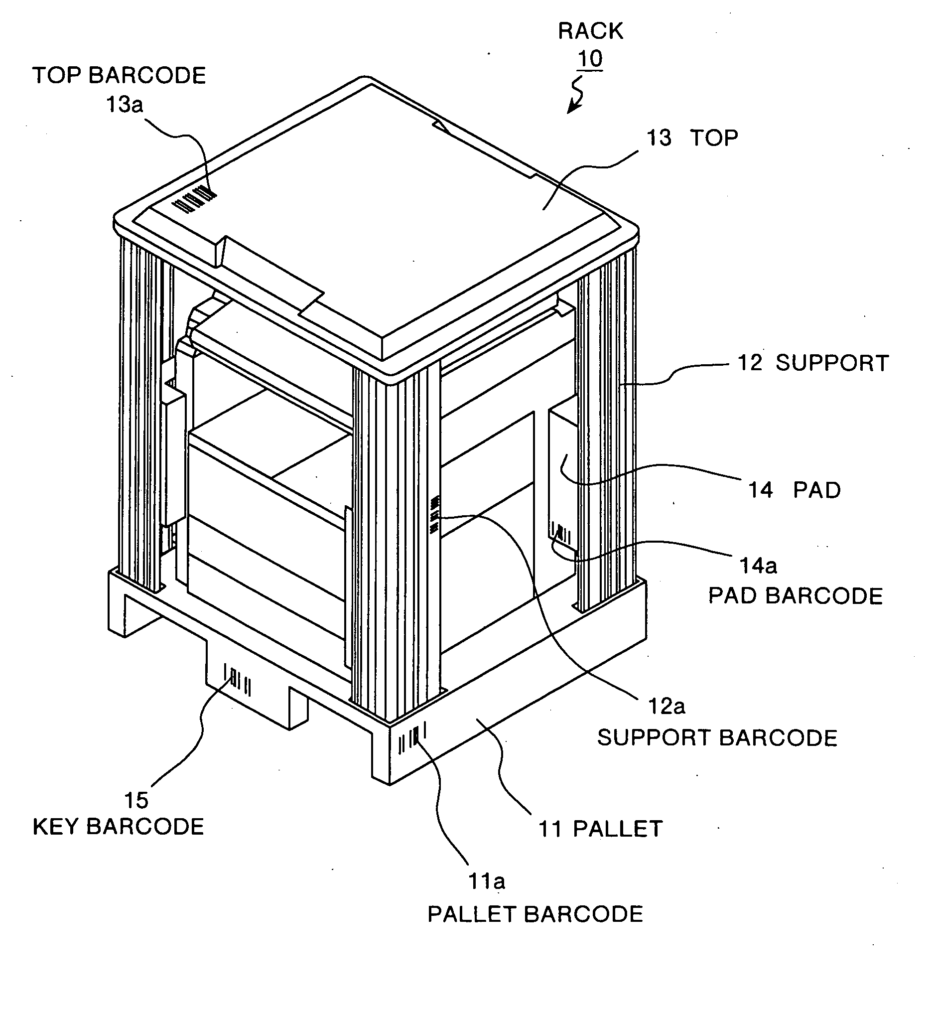
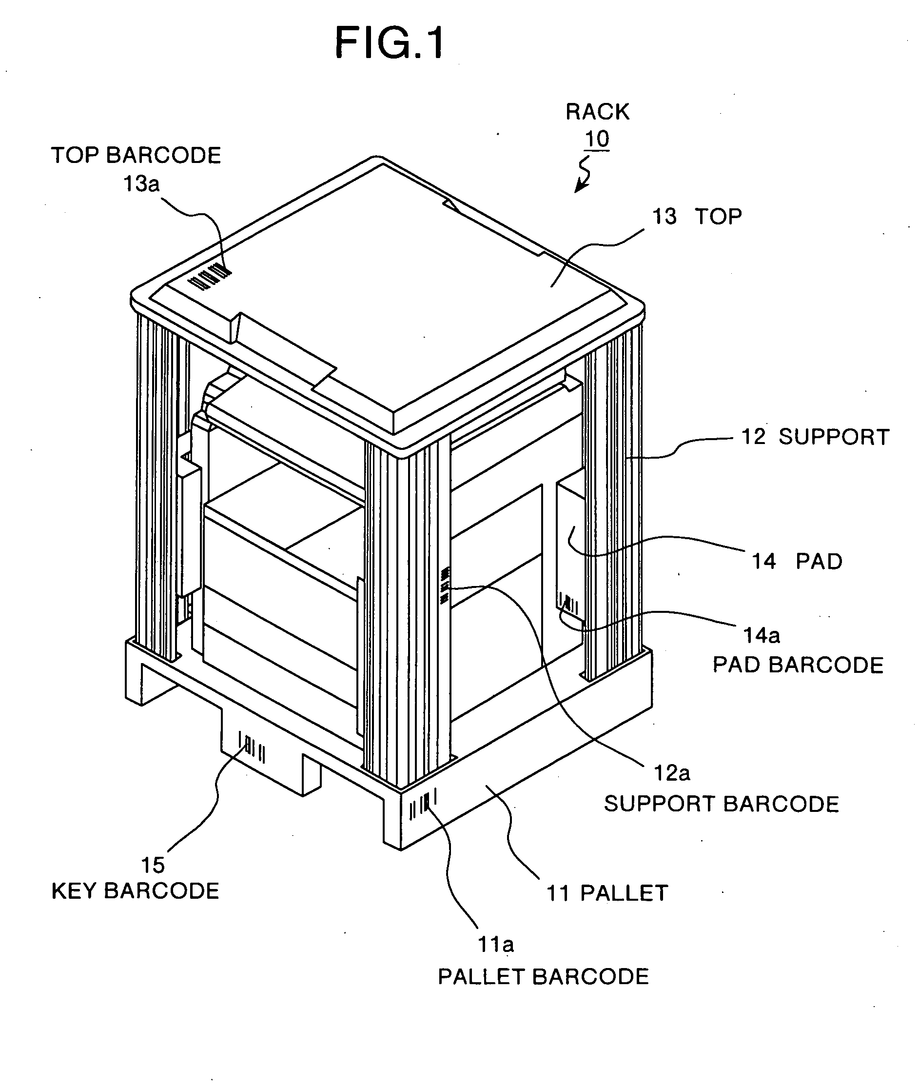
[0068] A rack according to this invention will be explained. FIG. 1 is a perspective view showing a structure of the rack according to this embodiment. This rack 10 is assembled with pallet 11, supports 12, top 13, and pads 14 so that the rack can be disassembled.

[0069] The pallet 11 has two legs and a loading plate integrally formed with these legs, and both of the legs are placed on the installation surface such as a floor surface. At this time, some space is formed between the installation surface and the loading plate so that a fork of a forklift can be inserted into the space.

[0070] The supports 12 are discretely and detachably fitted into four corners of the pallet after an article is loaded on the pallet. The top 13 is a cover that is provided over the upper parts of the supports 12 and protects the upper side of the article. The pads 14 are shock absorbing members formed according to the shape of the article to be conveyed and detachably fixed to the support 12.

[0071] Such...

second embodiment

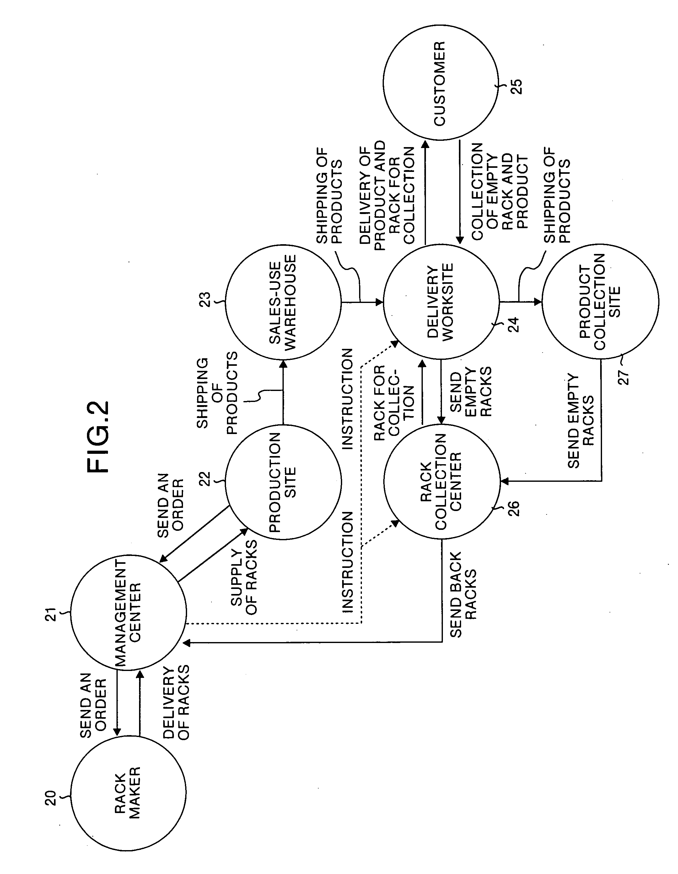
[0111] As explained above, in the second embodiment, even if the delivery data of a new product is different from the date for collecting an old product, a part of the rack components used to deliver the new product is reused for collection of the old product. Thus, the rack can be operated speedily and efficiently.

[0112] Although the first and second embodiments have presented the case where the delivery and the collection of products of the same type are executed, this invention is not limited by this case. That is, this invention is also applicable to a case where products of different types are handled. This case will be explained as the third embodiment.

[0113] More specifically, even if a product to be delivered to a customer 25 is an image formation device such as a copier and a product to be collected from the customer is electric appliances such as a refrigerator, the rack can be operated speedily and efficiently by reusing the rack components commonly used for delivery and...


PUM


Abstract

When a first article is to be delivered to a customer and a second article is to be collected from the customer, first rack components required for delivery of the first article and second rack components not required for delivery of the first article, yet required for collecting the second article, are specified. Delivery procedure and collection procedure of the articles using the specified first rack components and second rack components are instructed to a worksite. Accordingly, delivery and collection of the articles can be carried out by making efficient use of the rack components commonly used for the first article and the second article.

Description

FIELD OF THE INVENTION [0001] The present invention relates to a technology for managing racks used for packing, storing or delivering articles or products. BACKGROUND OF THE INVENTION [0002] Conventionally, when a maker receives an order of a product such as a copier or a facsimile from a customer, the product is packaged by a packaging member such as a corrugated board and delivered to the customer site, but disposal of the used packaging member is left to the customer. [0003] However, in order to deliver the product as a precision machine, some strength has to be given to the packaging member using the corrugated board. Resultantly, the packaging member becomes comparatively costly even though it is a disposable one. Referring to the recent environmental problems, if the disposable type of packaging member is used, the load of disposing the member is put more heavily on the customer. [0004] Therefore, in recent years, the case of repeatedly using a rack explained below for delive...

Claims


Application Information

Patent Timeline
Patent Type & Authority Applications(United States)
IPC IPC(8): B65D19/38B65D19/44
CPCB65D19/385B65D2203/06B65D19/44
Inventor ISHIKAWA, SAKAEISHIHARA, SATOSHIARAI, TOMOAKITANAKA, ISAMUSEKI, ISAMUARAI, HIDEAKINAGATSUKA, MASASHIYOSHIKAWA, KAZUHARUIKEDA, TAKASHI
Owner RICOH KK
Learn More