
Failure recovery for digital video recorders

a technology of failure recovery and digital video recorder, which is applied in the field of failure recovery of digital video recorders, can solve problems such as power failure, remote firmware update, and primary storage device failur

Inactive Publication Date: 2005-07-21
GENERAL INSTR CORP
View PDF11 Cites 84 Cited by
  • Summary
  • Abstract
  • Description
  • Claims
  • Application Information

AI Technical Summary

Benefits of technology

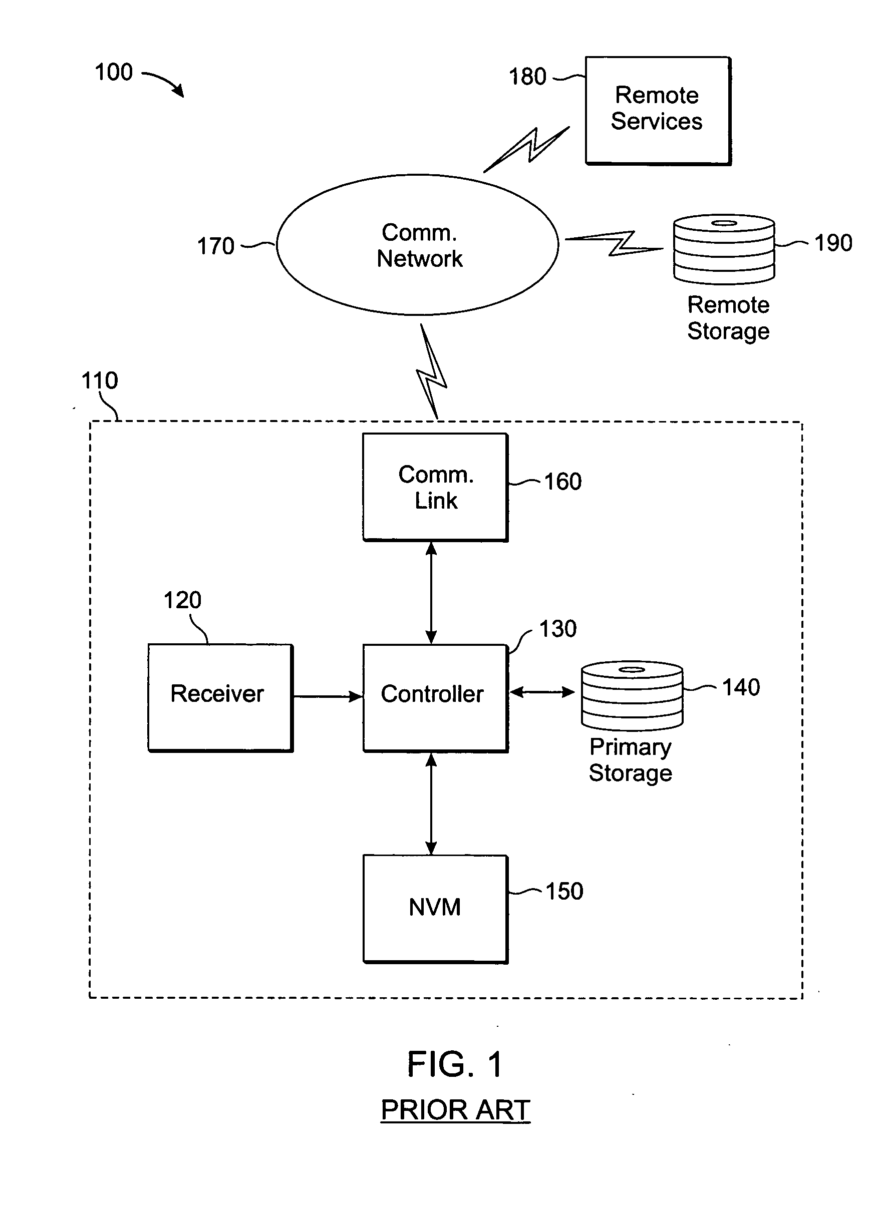
[0008] The digital video recorder device 110 comprises a receiver 120, a controller 130, a primary storage medium 140, non-volatile memory (NVM) 150 and a communications link 160. The receiver 120 receives video transmissions (e.g., via cable, satellite, airwaves, etc.) and converts them into a digital video stream that can be displayed, recorded, etc. The controller 130 is the “brain” of the digital video recorder system and performs most of the major functions of the digital video recorder device 110, such as descrambling and/or decoding video streams, storing/retrieving digital video to/from the primary storage medium 140, maintaining configuration information and firmware in non-volatile memory (NVM) 150, providing video playback, providing user interface functions, and communicating via the communications link 160 to provide such functionality as EPG, VOD, PPV and automatic firmware updates. Typically, the controller 130 is a microprocessor that operates according to a set of instructions stored within the DVR device. The primary storage medium 140 is typically a hard disk drive on which digital video recordings are stored. A catalog or index of those digital video recordings is maintained on the primary storage medium 140 as well.
[0009] In normal usage, a user will use the digita

Problems solved by technology

A variety of “disturbances” or interruptions can interrupt video recording.
These disturbances include: power failures, remotely initiated firmware updates, primary storage device failure, Emergency Alert broadcasts and loss of signal (LOS).
Another condition that can disturb normal DVR operation is insufficient primary storage space.

Method used


Image

  • Failure recovery for digital video recorders
  • Failure recovery for digital video recorders
  • Failure recovery for digital video recorders

Examples


Embodiment Construction

[0024] The present inventive technique deals with interruptions to recording (e.g., on a DVR) by means of a journaling system. A record of the journaled information is kept in non-volatile memory (NVM). In this way, if the video recorder is reset (e.g., power failure or remote firmware update), there is a record in NVM of what the recorder was doing when it was interrupted and at what point it was interrupted. Based on the stored “journal,” the recorder can determine what course of corrective action to take. Further, the recorder keeps a “backup copy” of the catalog (HDD directory or index) in secondary storage. This secondary storage can be provided by NVM or on another storage medium (e.g., a disk drive on a LAN to which the recorder is connected, or on a remote network storage device such as an Internet-connected file server).

[0025] As described hereinabove with respect to FIG. 1, a DVR typically includes a “controller” (see 130, FIG. 1), which executes a set of instructions sto...


PUM


Abstract

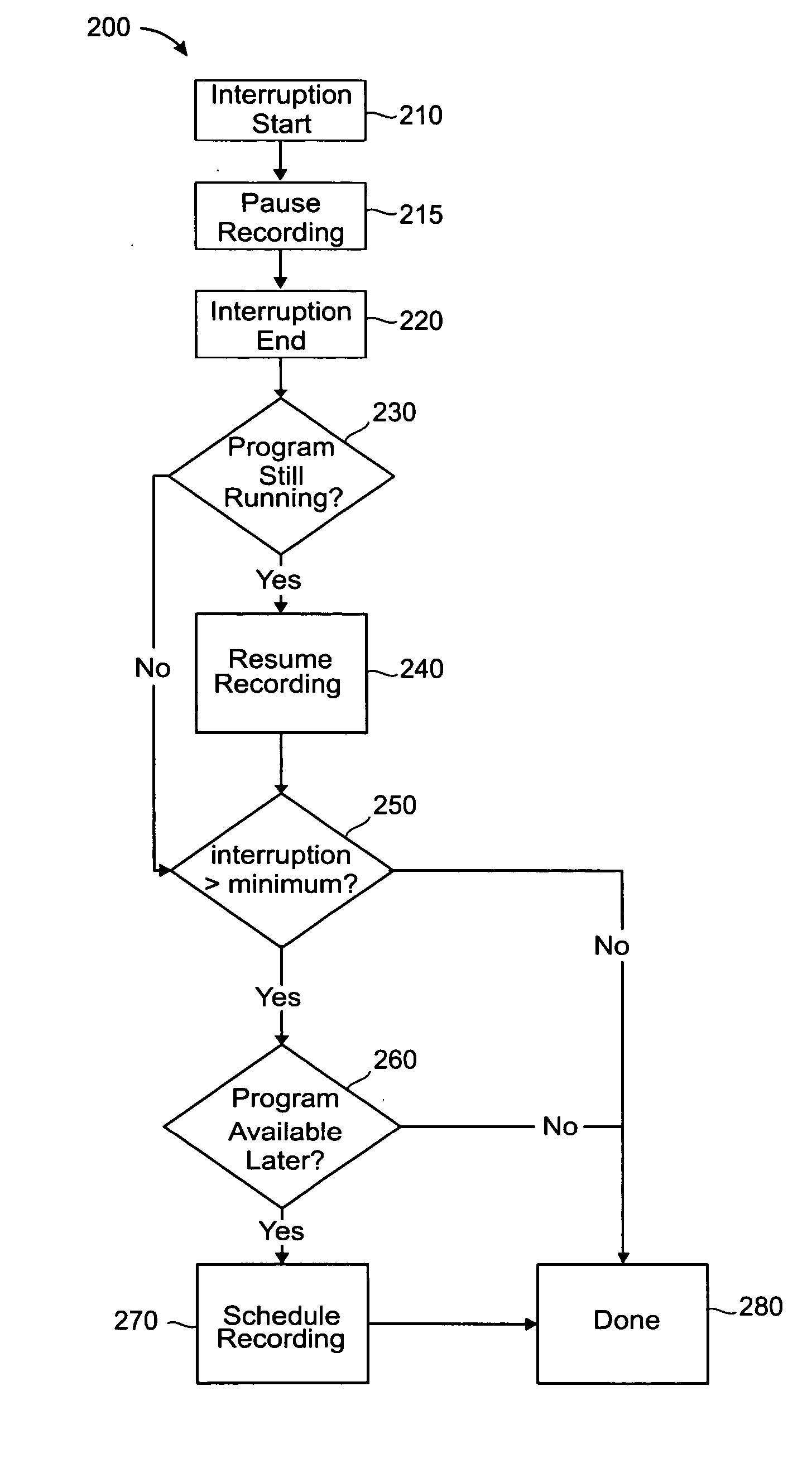
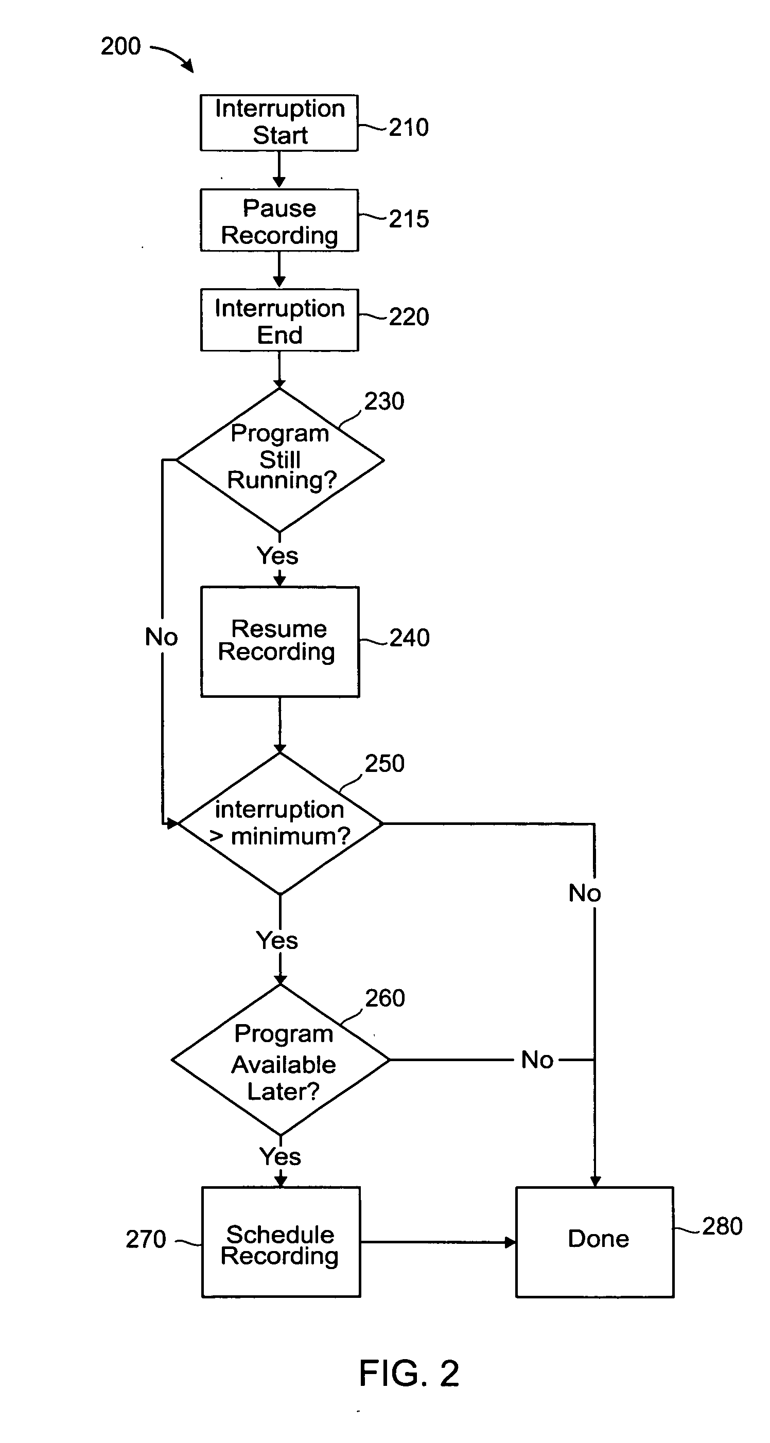
A method for DVR (digital video recorder) recovery from interruptions is described. Interruptions include power failures, primary storage device failure, Emergency Alert broadcasts, loss of signal (LOS), etc. Upon detecting that an interruption has occurred, the DVR determines the duration of the interruption and consults a saved “journal” of DVR operations to determine what it was doing when the interruption occurred. If a program that was being recorded prior to the interruption is still running when the interruption ends, recording is resumed. If the interruption is long, then the DVR searches an electronic program guide to see if the program is available for re-recording at a later time. If so, it schedules re-recording at that time. Recovery methods for insufficient primary storage space are also described.

Description

TECHNICAL FIELD OF THE INVENTION [0001] The present invention relates generally to digital video recording, and more particularly to direct video recording to a digital storage medium such as a hard disk drive. BACKGROUND OF THE INVENTION [0002] Recent advances in video compression and encoding technology have made low-cost digital video recording practical for consumer products. Over the last decade, digital video recording products in the form of DVD (Digital Versatile Disk) recorders and direct-to-disk recorders have gradually been making progress against older analog VCRs (Video Cassette Recorders) and are making a significant showing in the video marketplace. Once reserved exclusively for high-cost, high-end broadcast applications (e.g., instant replay), direct-to-disk digital video recording is now widely available to consumers in the form of digital video recorder (DVR) technology. [0003] Perhaps one of the most significant advantages of digital disk recording over tape recor...

Claims


Application Information

Patent Timeline
IPC IPC(8): G06F11/00G11B20/18H04N1/047H04N5/76H04N5/765H04N5/781H04N5/907H04N17/06
CPCG11B27/36H04N5/765H04N5/781H04N5/782H04N5/907H04N9/7921H04N21/47214H04N21/2747H04N21/4135H04N21/4147H04N21/42661H04N21/4335H04N21/43622H04N9/8042
Inventor ELCOCK, ALBERT F.GARRISON, WILLIAM J.
Owner GENERAL INSTR CORP
Learn More