
Bag with active ventilation

Inactive Publication Date: 2005-07-28
FOUTS KENNETH B II
View PDF24 Cites 21 Cited by
  • Summary
  • Abstract
  • Description
  • Claims
  • Application Information

AI Technical Summary

Benefits of technology

[0009] In accordance with the purposes of the present invention as described herein, a new and improved bag is described. The present invention includes a bag having an interior and exterior defined by at least one panel. Additionally, the bag includes fan, which may be solar powered or battery powered, with an air intake and exhaust, the air intake being disposed toward the exteri

Problems solved by technology

After participating in a sporting event, an individual's sporting equipment may often be damp or wet from perspiration or from use in the snow or ice.
Problematically, many of these bags used for transporting equipment provide little or no ventilation of the articles stored inside.
Thus, when an individual transfers wet sporting equipment in a conventional bag, the articles stay wet and often produce mold or mildew.
Problematically, this wet equipment stored in a conventional bag will often omit a foul odor and not fully dry before an individual again desires use of the equipment.
This condition is unsanitary and undesirable for the user.
Moreover, prolonged wetness of this equipment may lead to premature wear due to deterioration and rot.
This requires a user to replace the sporting equipment at a shorter interval than desired, a time consuming and costly problem.
Additionally, many individuals who utilize this equipment are not always in an area where they have access to conventional power supplies and drying equipment, such as a traditional clothes dryer.
Furthermore, these individuals may have the need for repeated use of this equipment over a several day period.
However, passive ventilation does not adequately dry the articles in a short enough time before an individual again desires their use.
Furthermore, when a bag is filled to capacity, the passive ventilation will not adequately supply ventilation to all of the articles in the bag.

Method used


Image

  • Bag with active ventilation
  • Bag with active ventilation
  • Bag with active ventilation

Examples


Embodiment Construction

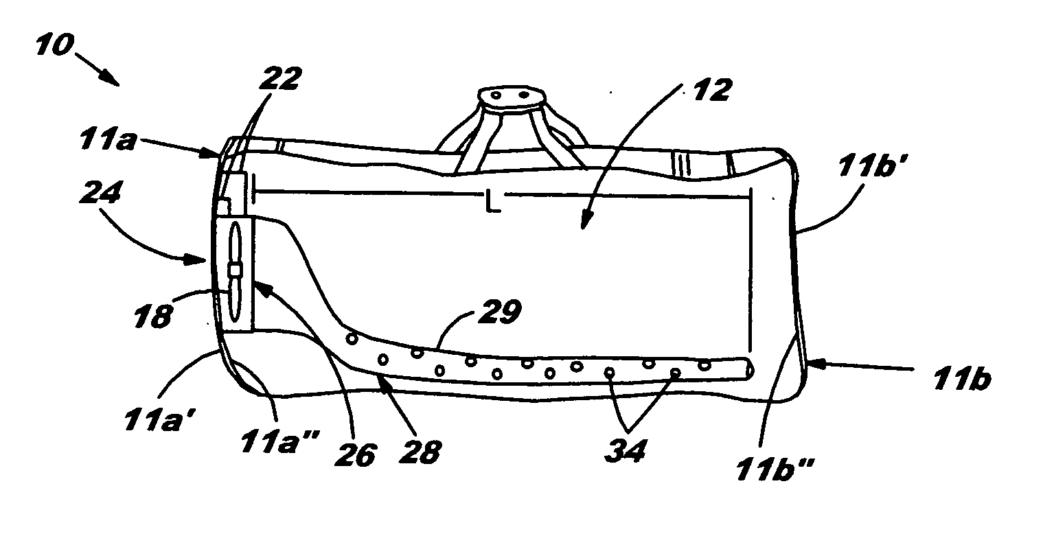
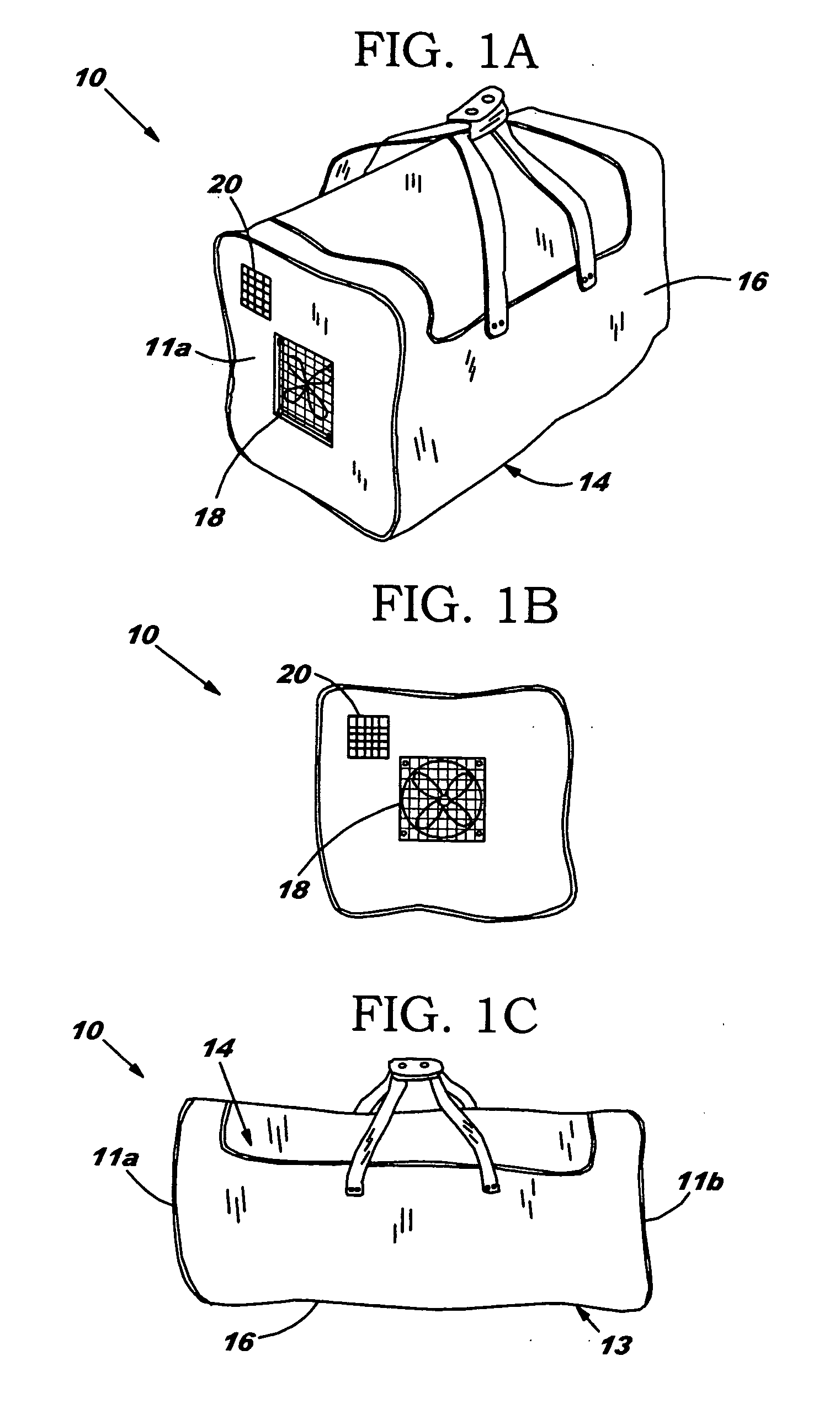
[0023] Reference is now made to FIG. 1A-1C and 2A illustrating the bag 10 of the present invention. As illustrated, the bag 10 includes an interior 12, an exterior 14 defined by at least one panel 16, and a fan 18. In one embodiment, the bag 10 takes the form of a cylindrical duffel bag 13 having a first end panel 11a and a second end panel 11b. The first end panel 11a and second end panel 11b each have a first side 11a′, 11b′ and a second side 11a″, 11b″. However, the bag 10 may be any shape, size, or design. The bag may also comprise any material such as nylon, canvas, leather, or any other.

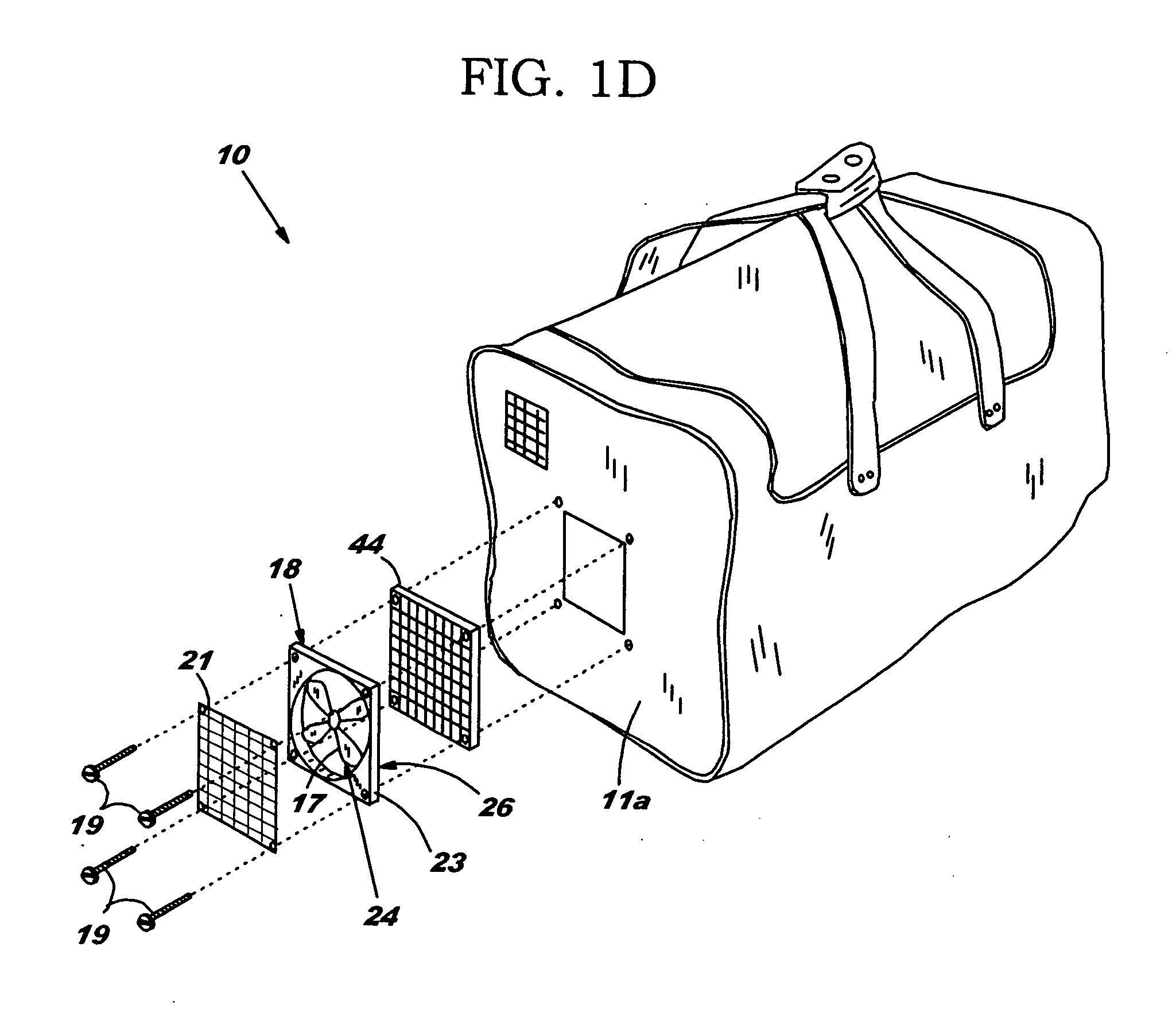
[0024] As shown in FIG. 1D, the fan 18 has an air intake 24 and an air exhaust 26. Furthermore, the fan 18 includes a fan cage 23 for supporting a fan blade 17 and a fan motor (not shown). Additionally, the fan 18 may include a grating 21 attached to the fan. The grating 21 helps protect an individual from injury from the fan blade 17 during use.

[0025] The fan 18 attaches to the bag 10 in var...


PUM


Abstract

A bag with active ventilation includes an interior and an exterior defined by at least one panel. The bag includes a fan, which may be solar powered, with an air intake and exhaust, the air intake being disposed toward the exterior and the exhaust being disposed toward the interior. The bag includes at least one conduit fluidly connected to the exhaust for distributing air from the intake to the interior during use. Additionally, the bag may include a bladder having a first panel, a second panel, and a plurality of vents for distributing air to the interior of the bag. The bladder also includes supports that prevent compression of the bladder when a load becomes placed on it, such as when articles become placed in the bag. Thus, the supports allow air to distribute through the bladder to all parts of the bag regardless of the bag contents.

Description

[0001] This application claims the benefit of U.S. Provisional Patent Application Ser. No. 60 / 536,126, filed Jan. 13, 2004.TECHNICAL FIELD [0002] The present invention relates generally to a bag for storing articles, such as a duffel bag for storing sports equipment, and more specifically, to a bag having a fan for active distribution of air to the interior of the bag. In other aspects the bag includes a conduit, which may include a tube or manifold, and a bladder for distributing air inside the bag. Moreover, the fan may utilize solar power or a rechargeable power source and incorporate a filter utilized for air freshening. BACKGROUND OF THE INVENTION [0003] Individuals participate in physical activities on a daily basis. From recreational exercising for fitness to participating in organized sports, almost everyone joins in some level of physical activity. Many individuals own and utilize specialized equipment for use with these activities. For instance, an individual may own runni...

Claims


Application Information

Patent Timeline
IPC IPC(8): A43D3/14A45C3/00A45C15/00A47L23/20F26B9/00F26B21/00
CPCA43D3/1408A45C3/00A45C15/00F26B21/006A47L23/20F26B9/003F26B9/006A45C2003/007
Inventor FOUTS, KENNETH B. II
Owner FOUTS KENNETH B II
Learn More