Universal projector mount

Active Publication Date: 2005-07-28
LEGRAND AV INC
View PDF21 Cites 44 Cited by
  • Summary
  • Abstract
  • Description
  • Claims
  • Application Information

AI Technical Summary

Problems solved by technology

Projectors, particularly LCD, CRT, and DRP projectors designed for frequent use in a setting such as described above are quite expensive.
In addition, the spaces where the projector is installed may be left unsecured for periods of time or left unattended.
Consequently, a problem is that project

Method used


Image

  • Universal projector mount
  • Universal projector mount
  • Universal projector mount

Examples


Embodiment Construction

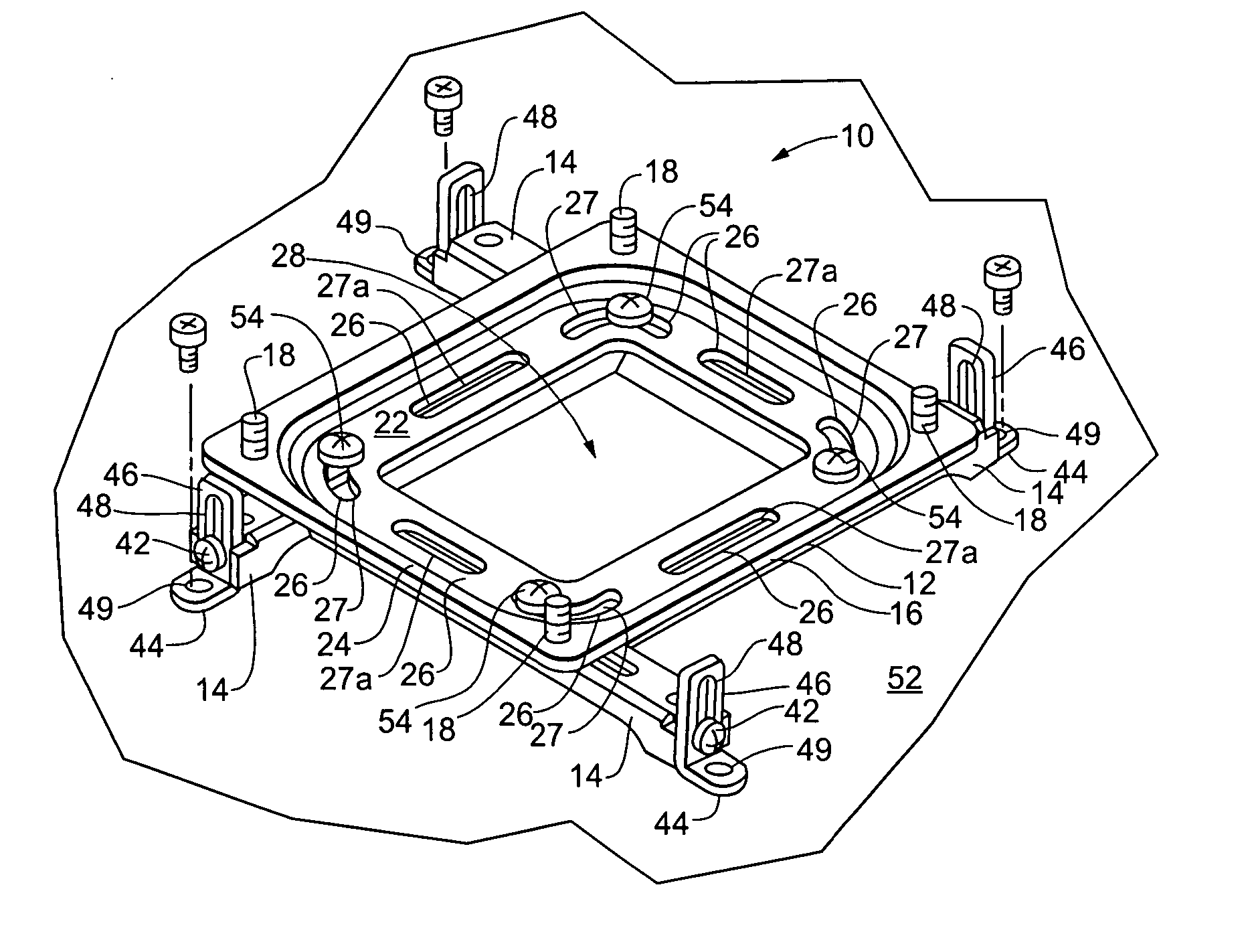
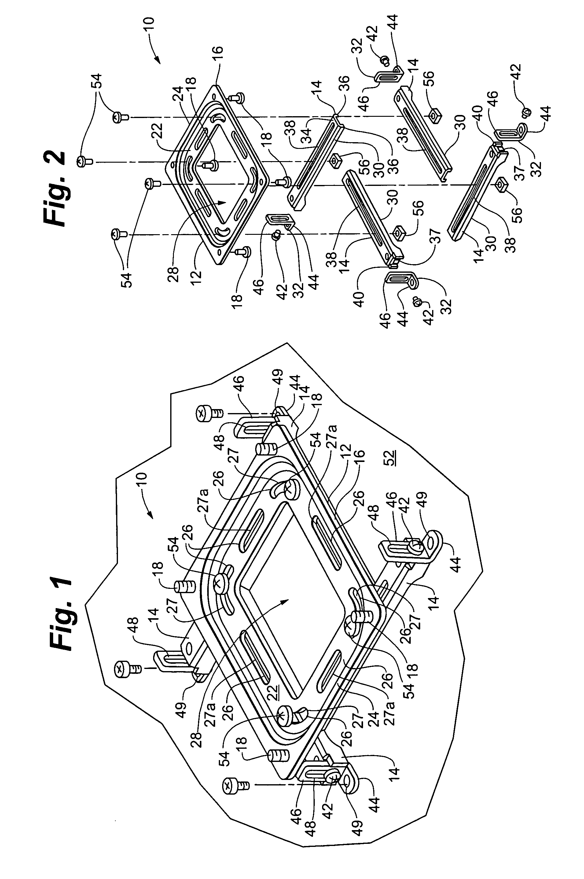
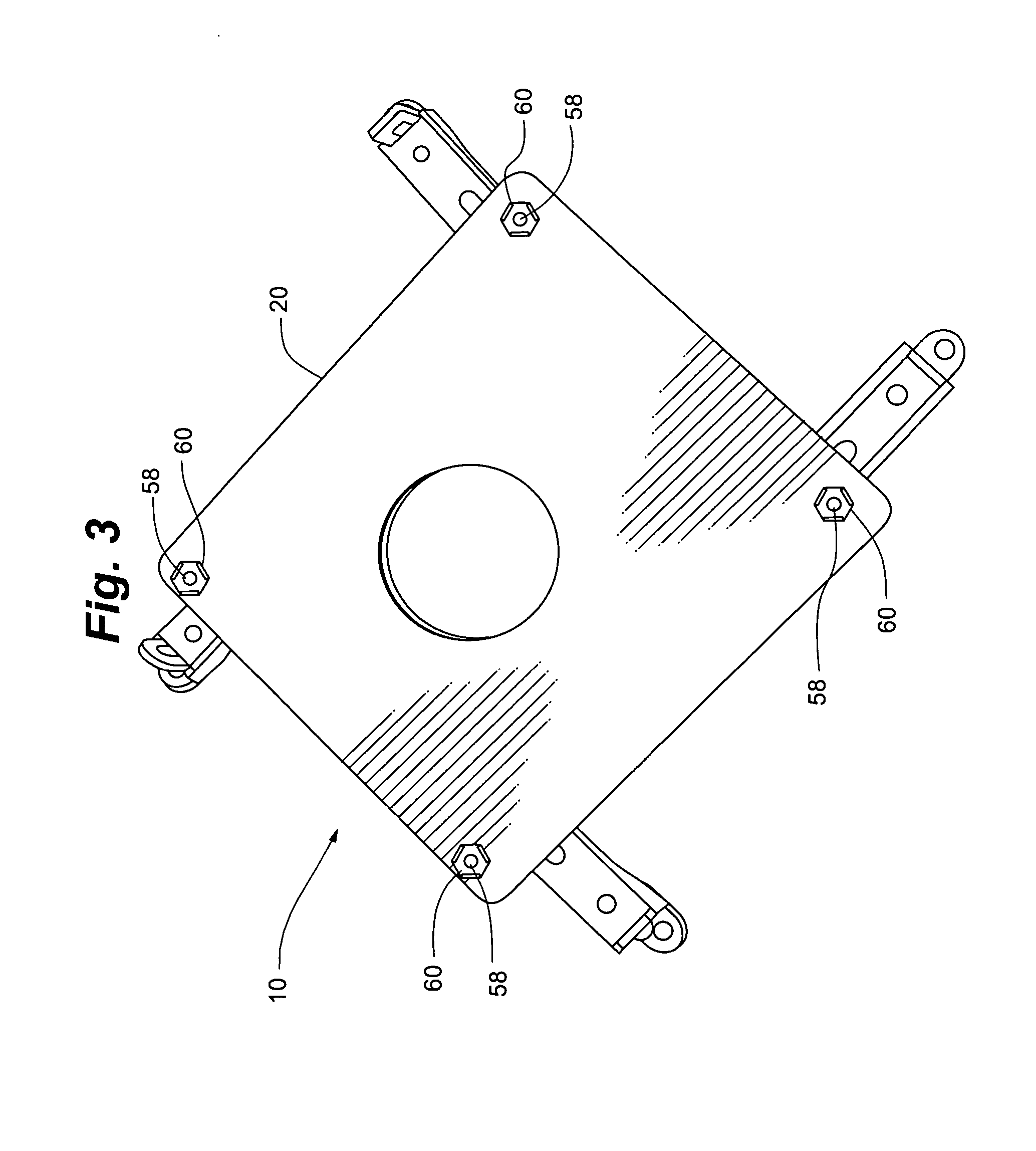
[0020] The universal projector mount 10 of the present invention, as depicted in FIGS. 1 and 2, generally includes a mount interface 12 and arms 14. Mount interface 12 generally includes central member 16 having studs 18 for detachably receiving an overhead projector mount 20. Overhead projector mount 20 is known in the art and more fully described in co-pending U.S. Utility patent application Ser. No. 10 / 821,659, commonly owned by the owners of the present invention and hereby incorporated herein in its entirety by reference.

[0021] Central member 16 has a recessed portion 22 recessed from peripheral margin 24. Elongate slots 26 are defined in recessed portion 22 and arranged just inside peripheral margin 24. Elongate slots 26 include curved slots 27 at the corners and generally straight slots 27a along the sides. Central aperture 28 may be provided if desired to lighten the structure.

[0022] Each arm 14 includes elongate beam portion 30 and foot 32. Elongate beam portion 30 may ha...


PUM


Abstract

A universal projector mount that can be fitted to mount projectors of a variety of different makes and models. The invention includes multiple adjustable arms coupled with an interface plate that is, in turn, attached to a standard projector mount on the fixed structure from which the projector is supported. The arms are adjustable radially and longitudinally to virtually any position so as to accommodate various fastener or fastener receiving locations on different makes and models of projectors.

Description

RELATED APPLICATIONS [0001] This application claims the benefit of U.S. Provisional patent application 60 / 538,634 filed Jan. 23, 2004 and 60 / 637,710 filed Dec. 21, 2004 both entitled Universal Projector Mount. Both of the above referenced applications are incorporated herein by in their entirety by reference.FIELD OF THE INVENTION [0002] The present invention relates generally to mounts for projectors. More particularly, the present invention relates to a universal mount for a projector. BACKGROUND OF THE INVENTION [0003] Visual projection systems are commonly used for entertainment and displaying, and presenting visual information to groups of people. Such visual projection systems typically include a projector unit and a projection screen. [0004] In spaces such as classrooms, conference rooms, and public assembly halls, where the space is often used for presentations, and in home entertainment rooms, it is common that the projector unit be installed as a more or less permanent fix...

Claims


Application Information

Patent Timeline
IPC IPC(8): F16M11/04
CPCF16M11/04F16M11/12F16M11/043
Inventor FRIEDERICH, STEVENDITTMER, JAY
Owner LEGRAND AV INC
Why Eureka
Try Eureka