Passive safety system and determination device

a safety system and determination device technology, applied in the direction of pedestrian/occupant safety arrangement, instruments, tractors, etc., can solve the problem of inability to properly determine the severity of accidents

Inactive Publication Date: 2005-07-28
DENSO CORP
View PDF28 Cites 8 Cited by
  • Summary
  • Abstract
  • Description
  • Claims
  • Application Information

AI Technical Summary

Benefits of technology

[0009] With this configuration, the determination device can determine the severity of collision based on the acceleration waveform produced only by a single sensor. Thus, the severity determination is reliably performed.

Problems solved by technology

If a malfunction occurs in one of the sensors, the severity may not be properly determined.

Method used


Image

  • Passive safety system and determination device
  • Passive safety system and determination device
  • Passive safety system and determination device

Examples


Embodiment Construction

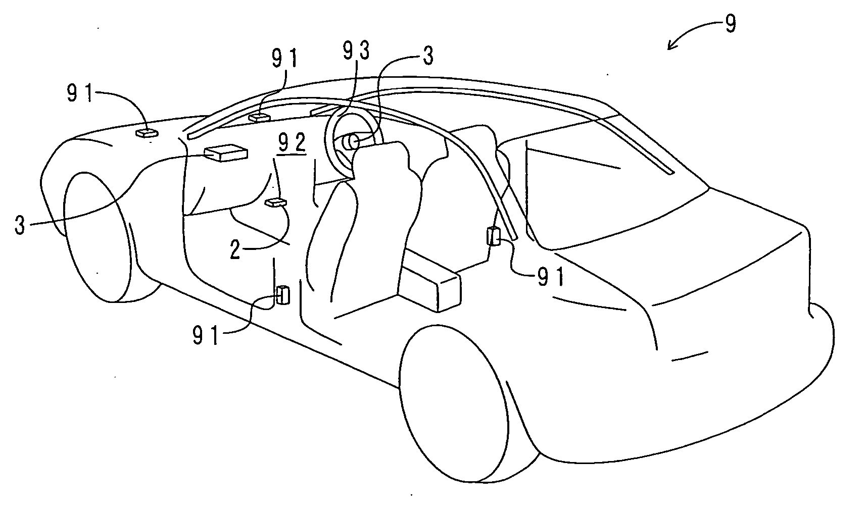
[0025] The preferred embodiments of the present invention will be explained with reference to the accompanying drawings.

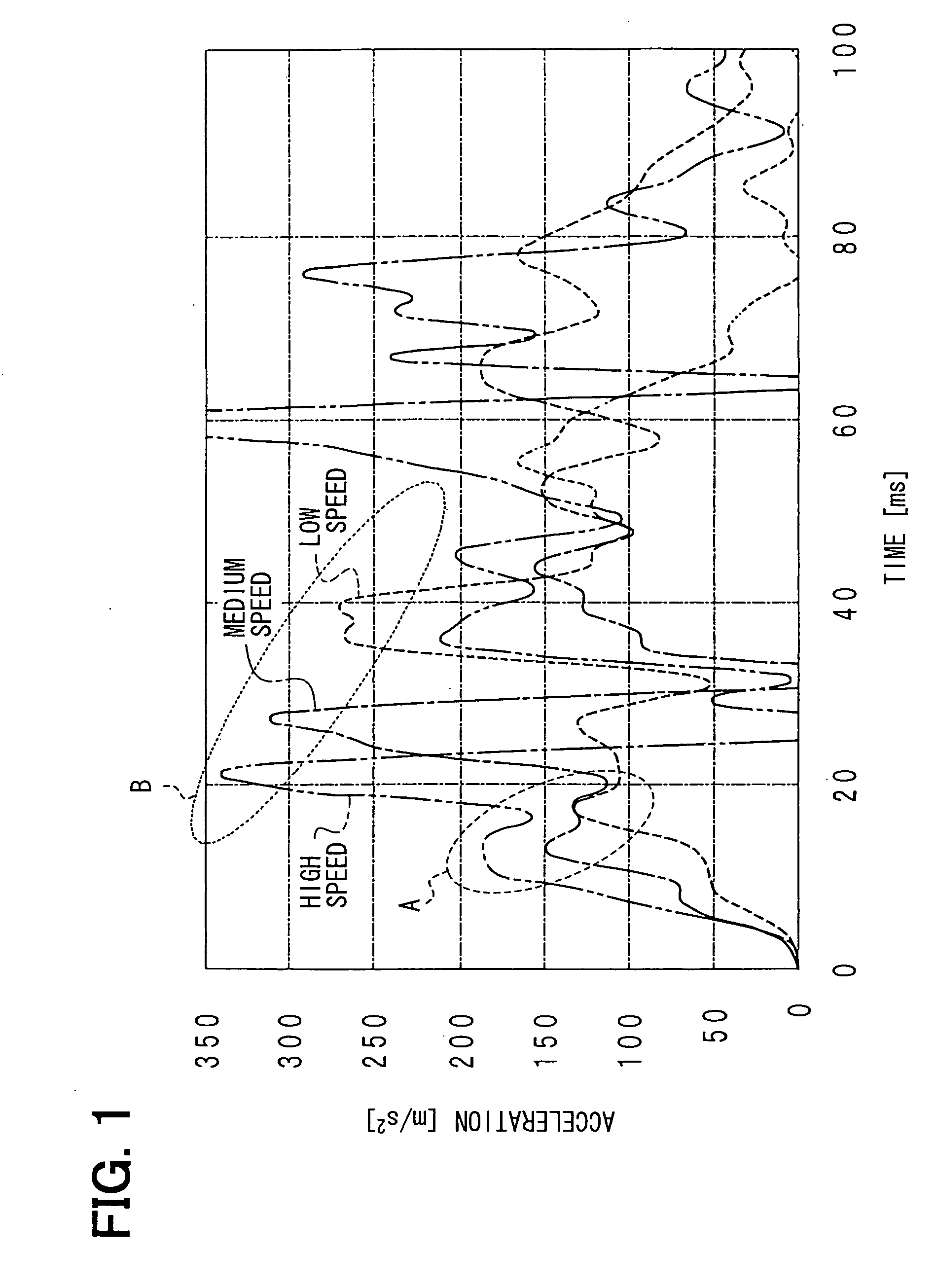
[0026] Severity of a collision in an accident becomes higher as a speed of a vehicle, which is a relative speed of a vehicle to an object, increase and the severity becomes lower as the speed of the vehicle decrease. Namely, the severity of a collision can be determined based on an acceleration waveform produced by an acceleration sensor.

[0027] Examples of high speed (30-35mph), medium speed (20-23mph), and low seed (under 16mph) acceleration waveforms are shown in FIG. 1. Peaks that indicate a structural characteristic of a vehicle appears in each waveform. The peaks in dashed-line circle A and the peaks in dashed-line circle B are referred to as the first peaks and the second peaks, respectively. Heights of the first peaks and the second peaks increase as a vehicle speed increases. The peak of the medium speed waveform is higher than that of the low speed wavef...


PUM


Abstract

A determination device includes a single acceleration sensor for measuring an acceleration of a vehicle and a determination circuit for determining severity of a collision in an accident. A plastic deformation pulse detection section and an elastic deformation pulse detection section of the determination circuit detect a plastic deformation pulse and an elastic deformation pulse, respectively, from a waveform of measured accelerations. A severity determination section of the detection circuit determines the severity of a collision based on a correlation between a vehicle speed and a plastic deformation pulse, and a correlation between the vehicle speed, the plastic deformation pulse, and an elastic deformation pulse.

Description

CROSS REFERENCE TO RELATED APPLICATION [0001] This application is based on and incorporates herein by reference Japanese Patent Application No. 2004-20537 filed on Jan. 28, 2004. FIELD OF THE INVENTION [0002] The present invention relates to a passive safety system for protecting an occupant of a vehicle against injury, and a determination device included in the passive safety system. BACKGROUND OF THE INVENTION [0003] A determination device for a passive safety system is proposed in JP-A-11-194137. In the passive safety system, an airbag is inflated in two steps using a satellite sensor and a floor G sensor. The satellite sensor is disposed at the front part of a vehicle and the floor G sensor is disposed in an electronic control unit ECU that is located under the instrument panel above the floor tunnel. The airbag system includes two inflators. The determination device detects the difference in phase between two acceleration waveforms obtained from the satellite sensor and the flo...

Claims


Application Information

Patent Timeline
Patent Type & Authority Applications(United States)
IPC IPC(8): B60R21/00G01P15/00B60R21/01B60R21/0136B60R21/015B60R21/16B60R22/48
CPCB60R21/0132B60R21/0156B60R21/0136B60R21/01332
Inventor HIGUCHI, HIROSHIIDE, SEIYA
Owner DENSO CORP
Why Eureka
Try Eureka