Animated radar signal display with fade

Inactive Publication Date: 2005-07-28
GOVERNMENT OF THE UNITED STATES AS REPRESENTED BY THE SEC OF THE NAVY
View PDF17 Cites 9 Cited by
  • Summary
  • Abstract
  • Description
  • Claims
  • Application Information

AI Technical Summary

Benefits of technology

[0018] In yet another aspect of the invention a method of displaying visually realistic raw radar signals comprises defining initial conditions, clearing a back buffer, shrinking a viewport for reducing texture size, applying an initial alpha value

Problems solved by technology

The properties of analog signals are different from the properties of digital signals resulting in differences in t

Method used


Image

  • Animated radar signal display with fade
  • Animated radar signal display with fade
  • Animated radar signal display with fade

Examples


Embodiment Construction

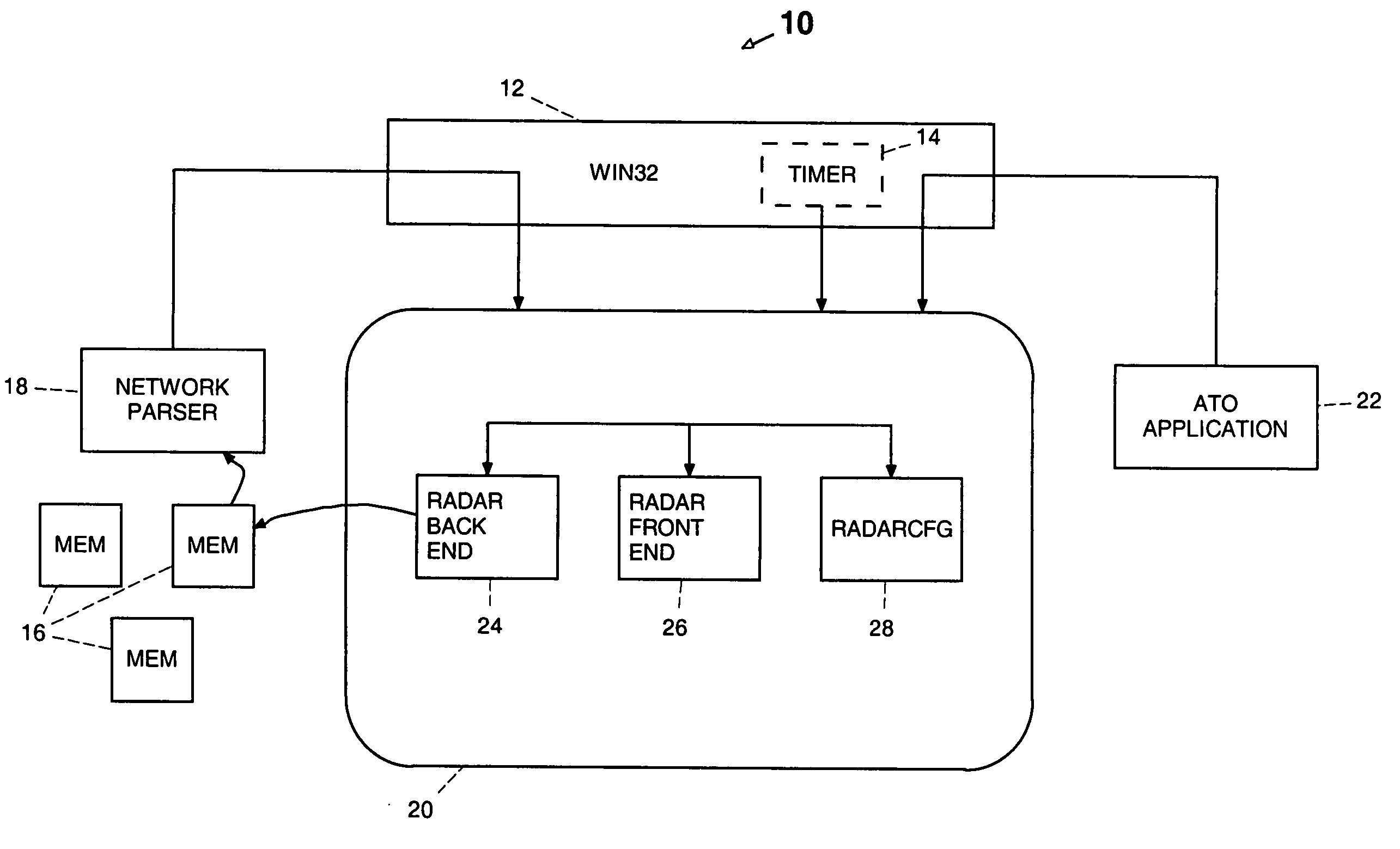
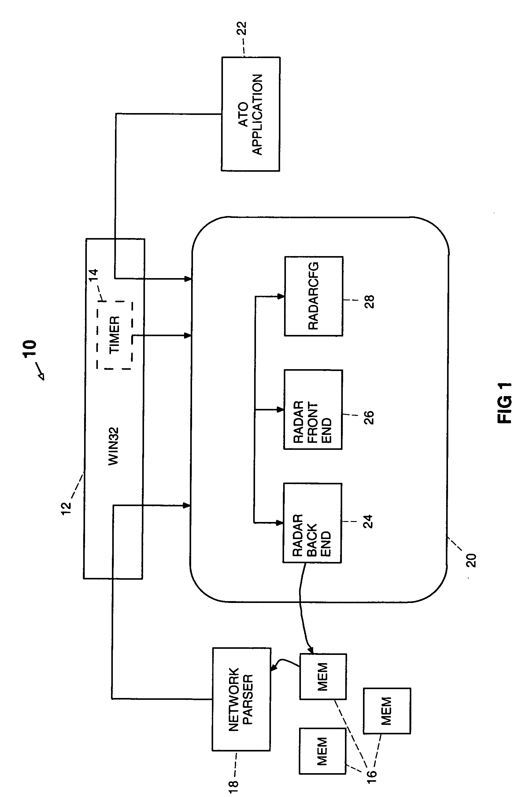
[0026] Referring to FIG. 1 an embodiment of a message passing architecture of a simulated RADAR system is shown generally at 10. The architecture includes a WINDOWS message-passing interface 12, which includes a timer 14. Although the present embodiment uses the WINDOWS operating system, it is within the skill of the art to select an operating system based on LINUX, UNIX or other operating system. The architecture further includes memory modules 16, a network parser 18, a RADAR simulation application 20, and an Air Tactical Officer (hereafter ATO) application 22. The RADAR simulation application receives incoming data and messages from the WINDOWS message-passing interface, the timer, the ATO application, the network parser and the memory.

[0027] The WINDOWS message-passing interface resides within the computer operating system program. The interface assists the WINDOWS operating system program by providing messages from it and other programs including RADAR target generators. As is...


PUM


Abstract

An exemplary embodiment of the invention relates to a computer-based program and system for displaying visually realistic raw radar signals. The computer program includes a RADAR display fade algorithm. The algorithm includes alpha blending and texture mapping for producing a slow fade. Use of two buffers and transfer of data between the buffers to produce a smooth update of the visual display while the sweep of the RADAR ray advances and new or updated RADAR contacts are displayed.

Description

CROSS-REFERENCE TO RELATED APPLICATIONS [0001] Not Applicable STATEMENT REGARDING FEDERALLY SPONSORED RESEARCH OR DEVELOPMENT [0002] Not Applicable REFERENCE TO A SEQUENCE LISTING, A TABLE OR A COMPUTER PROGRAM LISTING APPENDIX SUBMITTED ON A COMPACT DISC [0003] Not Applicable BACKGROUND OF THE INVENTION [0004] 1. Field of the Invention [0005] This invention relates to the field of RADAR simulation devices and more particularly to visual RADAR displays. [0006] 2. Description of the Related Art [0007] This invention relates generally to simulation graphics and more particularly to a method and a system for simulation of a display of raw RADAR data. [0008] Visual Radar displays are well known. From the time of the first RADAR to the present state of the art, it has been essential that the output of RADAR antenna signals be capable of human interpretation. Screens that have illumination properties, such as oscilloscopes, have long been used to display the processed antenna signals and ...

Claims


Application Information

Patent Timeline
IPC IPC(8): G01S7/04G09B9/54
CPCG09B9/54
Inventor LEGAN, LANCE ANDREW
Owner GOVERNMENT OF THE UNITED STATES AS REPRESENTED BY THE SEC OF THE NAVY
Why Eureka
Try Eureka