Accumulating conveyor system

a conveyor system and accumulator technology, applied in the field of conveyor systems, can solve the problems of exacerbated problems, various approaches to the noted problems in the prior art have proved unsatisfactory, and the product items are prone to slipping, so as to eliminate the undesirable accumulator effect, and reduce the occurrence of slipping

Inactive Publication Date: 2005-08-04
NEDCO CONVEYOR
View PDF6 Cites 15 Cited by
  • Summary
  • Abstract
  • Description
  • Claims
  • Application Information

AI Technical Summary

Benefits of technology

[0015] It is a further advantage of the present invention that the product singulation achieved in the singulator area of the conveyor system provides virtually zero product back pressure during either accumulation or straight through discharge of the product items. Since singulation of product items is effected with very low speed requirements of this area, the present conveyor system will handle an array of different materials without the impact noise or impact damage generated by conventional accumulators. This also will eliminate the undesirable “gel wobble” effect that occurs when a viscous liquid inside a product item container has a different spin characteristic than the container itself, resulting in product toppling particularly at opposing conveyor chain direction transfers. The present invention, therefore, permits glass containers, for example, to be conveyed and processed with much less ringing noise during accumulation than in convention arrangements, and without consequential impact damage to the containers.
[0016] There is additionally provided in the conveyor system of the present invention a dynamic transfer section for accelerating product movement from the slow speed accumulator section to the high speed singulation area where discharge is effected. It is an advantage of the present invention that the dynamic transfer section will not require dead plates, and movement of product through this transition will be stepless and without product bumping as in conventional transfer arrangements. Thus, product items can be conveyed in mass, yet the product transfer is controlled.
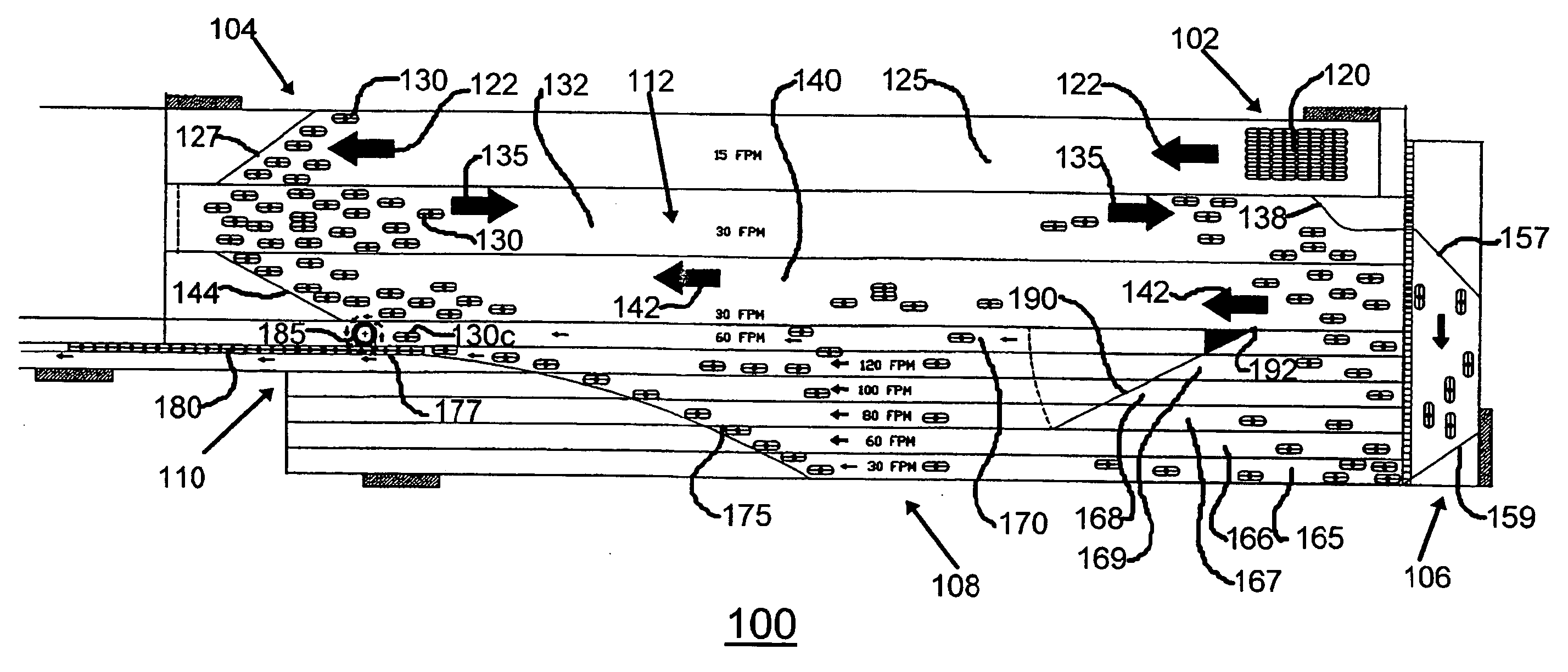
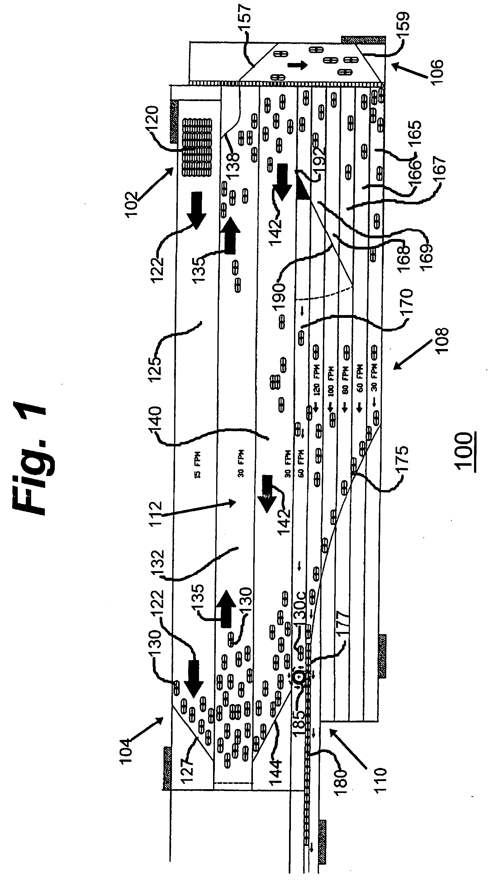
[0017] As will be described in greater detail herein, the high speed singulation area is provided with multiple speed-up lanes that provide controlled single file and oriented product discharge. A variable speed control arm is provided to control production flow balance between low and high speed areas. More specifically, the product items are directed to the exit area by the variable speed control arm, but as the quantity of products is increased, the control arm allows the product items to be directed to the accumulation region. This ensures efficient slow speed recirculation of the product items being conveyed with a nominal flow of product in the singulating area without diminishing the discharge rates. In a specific illustrative embodiment of the invention, a curved discharge rail enhances the discharge rates by physically pre-orienting product prior to single file release at discharge via the one or more exit ports of the conveyor system.
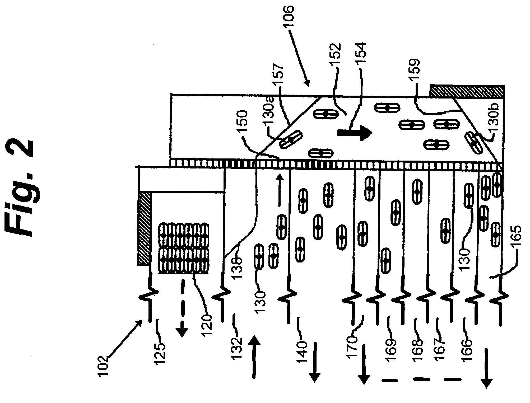
[0018] There is additionally provided in some embodiments of the conveyor system of the present invention a variable speed controlled impetus apparatus, illustratively in the form of a rotating orienter wheel disposed at the discharge region of the conveyor system. One benefit of the inventive orienter wheel is that it addresses and overcomes the bridge problems that occur when the product items being conveyed are not round. In operation, the impetus apparatus will automatically urge each product item toward the slow speed accumulation area for circulation therein. In some embodiments, the impetus device serves the additional purpose of accelerating the product items into the discharge channel of the exit port to ensure a back-to-back properly oriented single file exit of the product items.
[0019] The foregoing notwithstanding, the primary function of this conveyor system is to achieve low speed accumulation for product in excess of discharge production requirements and provide only enough product into high speed singulation discharge area to meet those requirements. As will be described herein, the present invention facilitates multiple in-feed product item entry points and single or multiple discharge ports.
[0020] In accordance with a first system aspect of the invention, there is provided a conveyor system for transporting a multiplicity of product items from an input portion to an output portion. The conveyor system is provided with an input station located at the input portion for receiving the multiplicity of product items. A first conveyor transports the product items from the input portion to a distal turnaround region. A second conveyor transports the product items from the distal turnaround region to a redistribution region. There is additionally provided a first product transfer arrangement for urging the product items from the first conveyor to the second conveyor. A plurality of exit conveyors are arranged to be parallel to each other for transporting the product items from the redistribution region to a product exit region located at the output portion. The plurality of exit conveyors are arranged to transport the product items at a respectively associated rates of transport. A product redistribution arrangement directs the product items to respective input ends of the plurality of exit conveyors. There is additionally provided a transverse element for directing the product items on the plurality of exit conveyors to a predetermined one of the plurality of exit conveyors.

Problems solved by technology

There are plural problems in the present state of the art in the field of conveyor systems that are used to deliver product items to downstream equipment, particularly in environments where the product items are delivered at varying rates, or in batches, to the conveyor system.
In addition to minimizing product bumping, which is related to product back pressure, it is important that the product items not be subjected to undue rotation, as such may cause viscous liquid therein to be spun at a different rate that the container itself, resulting in a “gel wobble” instability and consequential toppling of the product items.
The various approaches to the noted problems in the prior art have proven unsatisfactory.
Generally speaking, an effort to solve one problem exacerbates another, or creates a new problem.
In addition to requiring a large recirculating area by virtue of its continuous conveyor belt approach to achieving product item accumulation, the known arrangement does not redirect non-circular product items to a desired orientation in the exit port of the conveyor system.
Thus, product items having elongated cross-section may temporarily block the exit port, resulting in a single file exit having gaps.
In addition, the known arrangement is noisy in its operation as product items are directed to the accumulation area by bumping into product items that are to be discharged and thereby are deflected to the accumulation area.
Significant mechanical complexity and expense are associated with this known approach.

Method used


Image

  • Accumulating conveyor system
  • Accumulating conveyor system
  • Accumulating conveyor system

Examples


Embodiment Construction

[0034]FIG. 1 is a simplified schematic representation of a specific illustrative embodiment of the invention. As shown in this figure, an accumulating conveyor system 100 is generally configured to have a product receiving section 102, a product turnaround section 104, a product redistribution section 106, a product singularization section 108, a discharge section 110, and an accumulation section 112. In the operation of the specific illustrative embodiment of the invention, a plurality of product items in a batch 120 are deposited at product receiving section 102. Batch 120 of product items is transported in the direction of arrows 122 on conveyor surface 125 until it reaches product turnaround section 104.

[0035] At product turnaround section 104, batch 120 encounters a guide rail 127 whereupon the batch is disbanded into separated individual ones of product items 130. By operation of guide rail 127, product items 130 are diverted onto conveyor surface 133, where the direction of ...


PUM


Abstract

A conveyor system transports a multiplicity of product items from an input portion to an output portion and is provided with a first conveyor that transports the product items from the input portion to a distal turnaround region. A second conveyor transports the product items from the distal turnaround region to a redistribution region. A first product transfer arrangement urges the product items from the first conveyor to the second conveyor. A plurality of exit conveyors are arranged to be parallel to each other for transporting the product items from the redistribution region to a product exit region located at the output portion, and are arranged to transport the product items at a respectively associated rates of transport. A product redistribution arrangement directs the product items to respective input ends of the plurality of exit conveyors. There is additionally provided a transverse element for directing the product items on the plurality of exit conveyors to a predetermined one of the plurality of exit conveyors.

Description

RELATIONSHIP TO OTHER APPLICATION [0001] This application claims the benefit of Provisional Patent Application Ser. No. 60 / 541,300, filed on Feb. 2, 2004.BACKGROUND OF THE INVENTION [0002] 1. Field of the Invention [0003] This invention relates generally to conveyor systems, and more particularly, to an accumulating conveyor system that expels batch loaded product items in one or more single file outlet channels and accumulates the excess product items in response to the quantity of such product items being transported on plural exit conveyors. [0004] 2. Description of the Related Art [0005] There are plural problems in the present state of the art in the field of conveyor systems that are used to deliver product items to downstream equipment, particularly in environments where the product items are delivered at varying rates, or in batches, to the conveyor system. It is, in those situations, not only desired that the conveyor system accumulate the excess product items pending their...

Claims


Application Information

Patent Timeline
Patent Type & Authority Applications(United States)
IPC IPC(8): B65G37/00B65G47/68
CPCB65G2047/687B65G47/684
Inventor TARLTON, CURTIS S.
Owner NEDCO CONVEYOR
Why Eureka
Try Eureka