Confined space entry device and safety line for fall arrest

a technology of confined space and entry device, which is applied in the direction of safety belts, vehicles with cranes, transportation items, etc., can solve the problems of cumbersome movement and assembly of heavy sections, cumbersome manipulation of offsets, and insufficient light designs to carry the required loads for many applications

Inactive Publication Date: 2005-08-04
T A PELSUE
View PDF1 Cites 25 Cited by
  • Summary
  • Abstract
  • Description
  • Claims
  • Application Information

AI Technical Summary

Benefits of technology

[0010] In still another aspect of the invention, the davit assembly makes use of an asymmetric elbow, that is, an elbow with a longer leg and a shorter leg. Each of the legs is structured so that it can slidably engage and be removably secured to either one of the post and the extension arm. In this way, a single extension arm can be used to create two, different offset lengths, depending on whether the extension arm is connected to the longer leg of the elbow or the shorter leg of the elbow.
[0011] In yet another aspect of the invention, the confined space device incorporates a safety line connected to the lower end of the davit assembly or member, extending to and connecting to the upper end of the davit assembly or member. The safety line should have a tensile strength equal to or greater than the dynamic rating of the davit assembly or member; the reason being that should the member fail, the safety line would arrest the fall of a worker or person secured to the device.

Problems solved by technology

The use of such designs produces heavy sections that are cumbersome to move and assemble; other, lighter designs are often inadequate to carry the required loads for many applications.
Under the current art, in order to vary such offset, multiple, cumbersome pieces generally need to be brought to the site and kept available, and cumbersome manipulations are required before the offset can be changed.
The approaches of the current art to this matter often involve cumbersome shock-absorbing solutions.

Method used


Image

  • Confined space entry device and safety line for fall arrest
  • Confined space entry device and safety line for fall arrest
  • Confined space entry device and safety line for fall arrest

Examples


Embodiment Construction

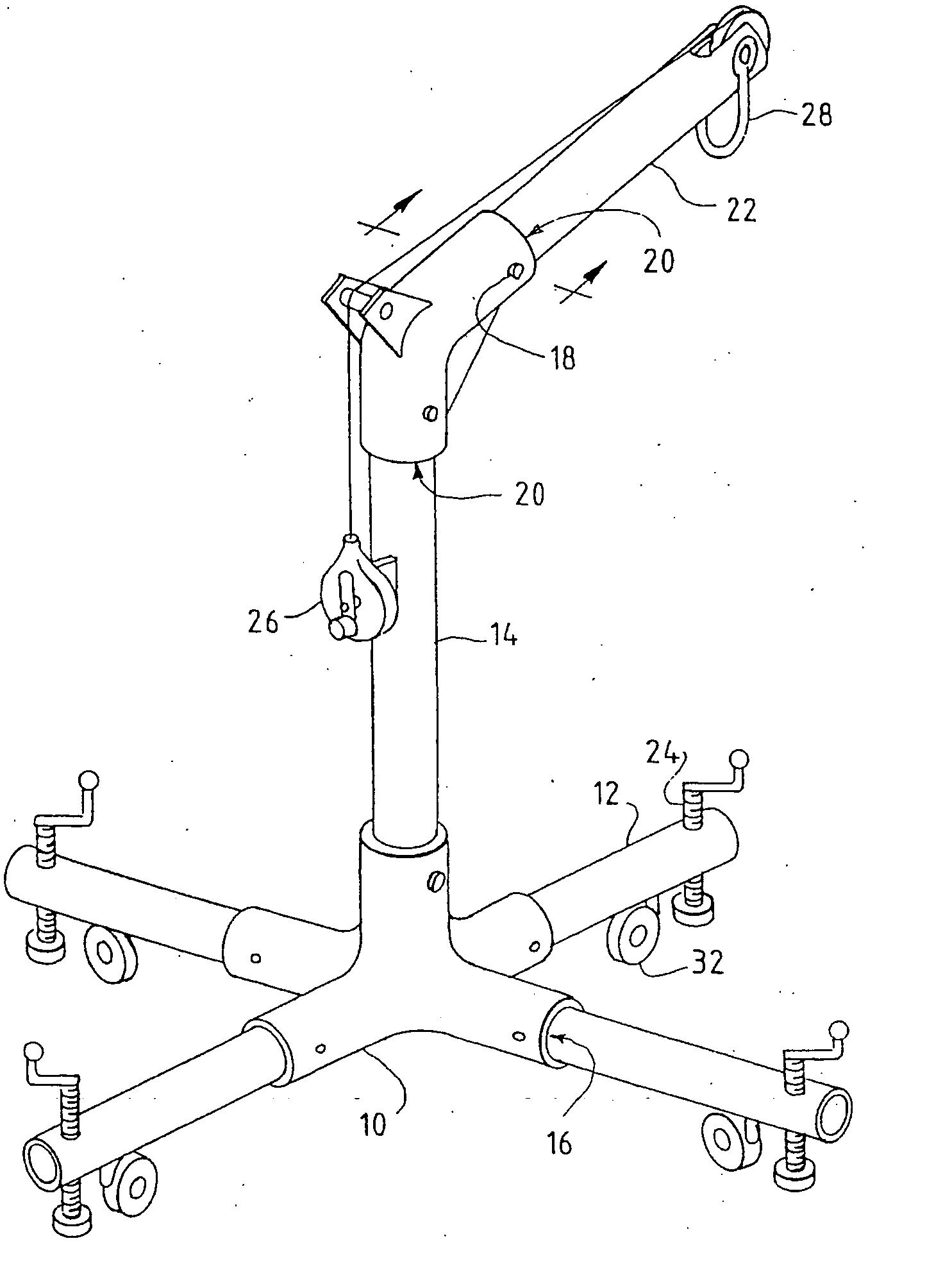
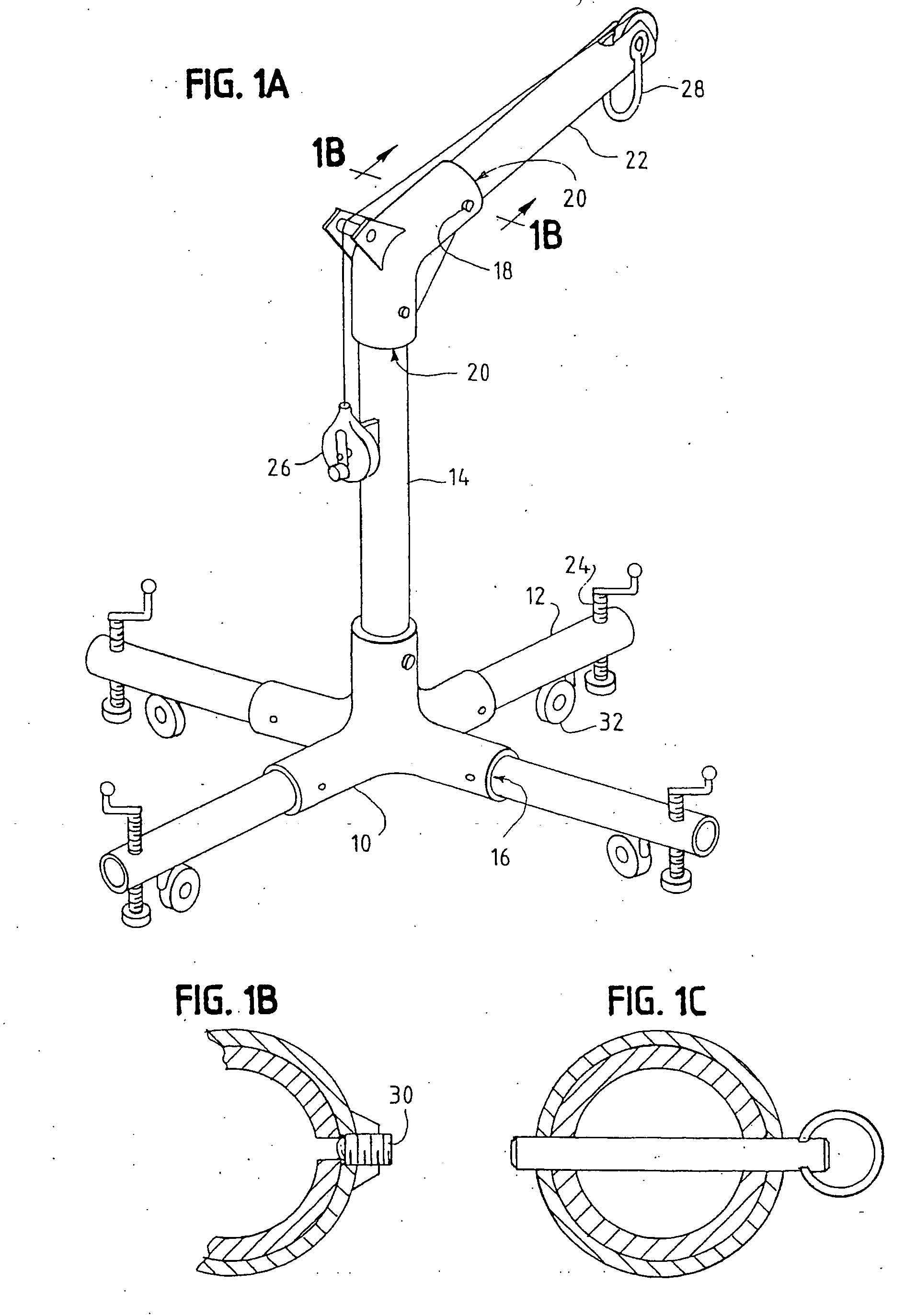
[0026] Referring to FIGS. 1A to 5, a confined space device, according to one preferred embodiment of the present invention, includes an “X” base frame 10 having four legs 12 connected to a vertical elongated section, post, or mast 14 through the use of a cast “X” base frame 10. Confined space devices often are used to provide high height anchorage or tie off; accordingly, in this application, the use of the term “confined space entry device” or “confined space device” includes the possibility of using such devices for high height anchorage.

[0027] The cast “X” base frame 10 receives leg tubes 12 by slidably inserting leg ends into corresponding openings in the cast “X” base joint 16. The vertical elongated section 14 of the structure extending vertically from the cast “X” base 10 terminates in an upper end which is slidably received in a corresponding structure in cast elbow 18. The opposing ends of elbow 18 and post or mast 14 are preferably joined in a manner similar to that used ...


PUM


Abstract

A confined space entry device has modularized components which allow the device to be readily reconfigured. In particular, the extension arm of the device is removably secured to one leg of an elbow, while a post or mast is removably secured to the other end of the elbow. The other end of the mast is removably secured to a base which supports the confined space entry device. In one version of the invention, the device includes tubular members made of a polymer composite material. In another version of the invention, the elbow is asymmetric about a central axis and is formed of cast aluminum. The device can include sets of different-length elongated members which can be interchanged with elongated members secured within the device. In yet another version of the invention, the device incorporates a safety line connected to a lower end of the davit assembly or member and extending to an upper end of the davit assembly or member. The safety line should have a tensile strength equal or greater than to the dynamic rating of the post; should the member break above the lower end, the safety line would arrest the fall of a worker or person secured to the confined space device.

Description

RELATED APPLICATIONS [0001] The present application relates to U.S. application Ser. No. 09 / 831,131 and PCT Application No. PCT / US00 / 27754 by common assignee.TECHNICAL FIELD [0002] The present invention relates to a confined space entry device and safety line for fall arrest. BACKGROUND ART [0003] Confined space entry products and devices are currently used in many applications requiring “man rated” lifting and lowering capabilities as described by OSHA and ANSI Regulations. These devices are typically rigid structures that must be carried manually to a work site and erected for a specific use. Typical uses are entry into manholes, tank manways, over the edges of walking / working surfaces, off the edges of power transformers, over bridge edges, into chimneys and flues, into underground tunnels, and any other locations where entry is made difficult due especially to space constraints. [0004] Since these devices generally need to be packed, transported, and carried manually to a desire...

Claims


Application Information

Patent Timeline
Patent Type & Authority Applications(United States)
IPC IPC(8): A62B1/04A62B1/06B60P1/00B60P1/54B60P3/055B62B1/00B66C23/48
CPCA62B1/04A62B35/0068B66C23/48B60P3/055B60P1/5471
Inventor PELSUE, BRADLEY A.
Owner T A PELSUE
Why Eureka
Try Eureka