Devices for storing a blanket to be supplied to a cylinder of a printing machine

a technology for printing presses and blankets, which is applied in printing presses, office printing, printing, etc., can solve the problems of individual printing plates being loose from suspension rails, changing pre-positioning, and requiring a very large structural space for printing plate readiness devices, etc., and achieves the effect of extremely low device structure heigh

Inactive Publication Date: 2005-08-11
KOENIG & BAUER AG
View PDF14 Cites 12 Cited by
  • Summary
  • Abstract
  • Description
  • Claims
  • Application Information

AI Technical Summary

Benefits of technology

[0013] The advantage which can be realized by the present invention consists, in particular, in that it is possible to change several dressings on a cylinder of a printing press rapidly and dependably at the same time, or at least in very rapid succession. By the actuation of a holding element, the dressing falls from a vertically upper storage position into a storage position located thereunder, from which lower storage position the dressing can be transported to the cylinder. By actuating the holding element, the stored dressing changes in free fall from its vertically upper storage position into the storage position located underneath. The actuation of the holding element preferably takes place by use of a controlled drive mechanism and can therefore be mech

Problems solved by technology

Because of the intended pivot movement of the printing plate hanging at the vertically offset suspension rails, the printing plate readiness device requires a very large structural space which, however, is not always available in printing presses.
The readiness position, which is remote from the cylinder, obstructs access to the printing group, which obstruction often causes problems in actual use, and is at least undesirable.
Moreover, because of acceleration forces which act on the printing plate readiness device, during the pivot movement, the danger arises that individual printing plates may come loose from their suspension rail, or may, at least, slip in it and may thereby change their pre-positioning.
This can negatively affect the depe

Method used


Image

  • Devices for storing a blanket to be supplied to a cylinder of a printing machine
  • Devices for storing a blanket to be supplied to a cylinder of a printing machine
  • Devices for storing a blanket to be supplied to a cylinder of a printing machine

Examples


Embodiment Construction

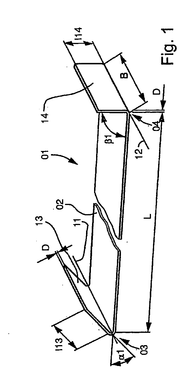
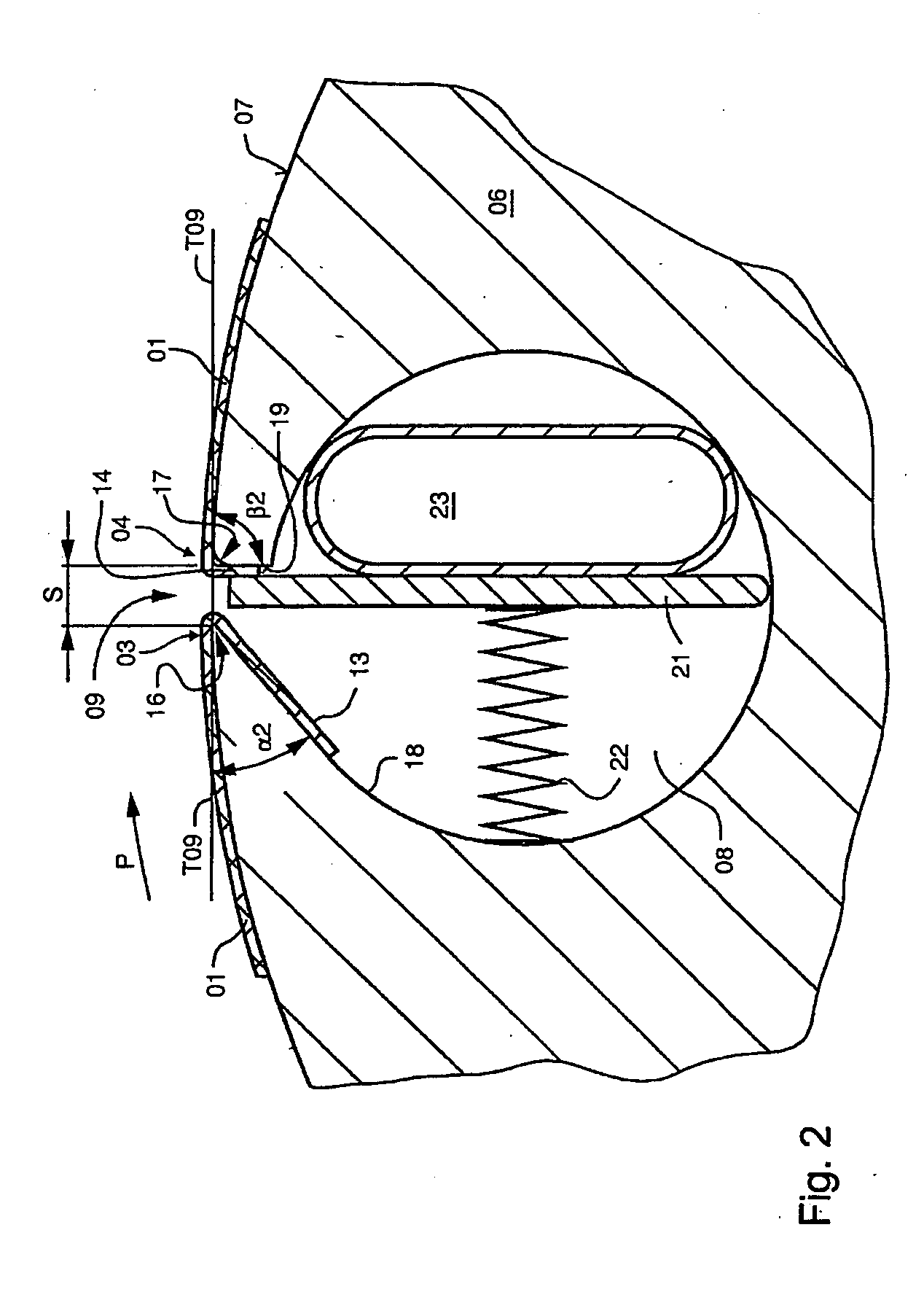
[0029] A dressing 01, as seen in FIG. 1, which, for example, is configured as a plate-shaped printing forme 01, or as a support plate for a printing blanket, has a substantially rectangular area of a length L and a width B. The length L can have measured values between 400 mm and 1300 mm, for example, and the width B can have measured values between 280 mm and 1500 mm, for example. Preferred measured values for the length L lie, for example, between 360 mm and 600 mm, and preferred values for the width B lie, for example between 250 mm and 430 mm. The rectangular area has a bearing area, which will be called bearing area 02 in what follows, on which bearing area 02 the dressing 01 rests when it is arranged on the surface 07 of a cylinder 06, as seen in FIG. 2. The reverse side of the bearing area 02 is a working area which, in case the dressing 01 is configured as a printing forme 01, is provided with a print image, or at least can be provided with a print image. The dressing 01 has...


PUM


Abstract

A device is used to store blankets or dressings which are to be supplied to a cylinder of a printing machine. A plurality of such blankets or dressings, which are to be applied to the cylinder adjacent each other and axially spaced, are stored next to each other. These blankets or dressings are stored vertically above a supporting surface, in at least two vertically offset planes. The offset planes form a first storage position and the supporting surface forms a second storage position once at least one of the blankets or dressings has been stored in the different planes.

Description

CROSS-REFERENCE TO RELATED APPLICATIONS [0001] This application is the U.S. National Phase, under 35 U.S.C. 371, of PCT / EP 2004 / 050161, filed on Feb. 19, 2004; published as WO 2004 / 085160 A1 on Oct. 7, 2004, and claiming priority to DE 103 14 344.0 filed Mar. 28, 2003, the disclosures of which are expressly incorporated herein by reference.FIELD OF THE INVENTION [0002] The present invention is directed to devices for storing a dressing to be supplied to a printing press. A plurality of dressings to be applied side-by-side to a cylinder of the printing press are stored side-by-side. BACKGROUND OF THE INVENTION [0003] A method and a device for making printing plates available is known from DE 44 42 574 C2. In a position of readiness, the printing plates are hung in two suspension rails, which rails extend parallel with respect to the cylinder and which are vertically offset in respect to each other. The rails are part of a printing plate readiness device and are pre-positioned. The pr...

Claims


Application Information

Patent Timeline
IPC IPC(8): B41F27/12B41F30/00B41F30/04B41L47/14
CPCB41F27/1206B41P2227/62B41P2227/11B41F30/04
Inventor SCHNEIDER, GEORGSCHAFER, KARL ROBERT
Owner KOENIG & BAUER AG
Why Eureka
Try Eureka