Brush-type deburring machine
- Summary
- Abstract
- Description
- Claims
- Application Information
AI Technical Summary
Benefits of technology
Problems solved by technology
Method used
Image
Examples
Embodiment Construction
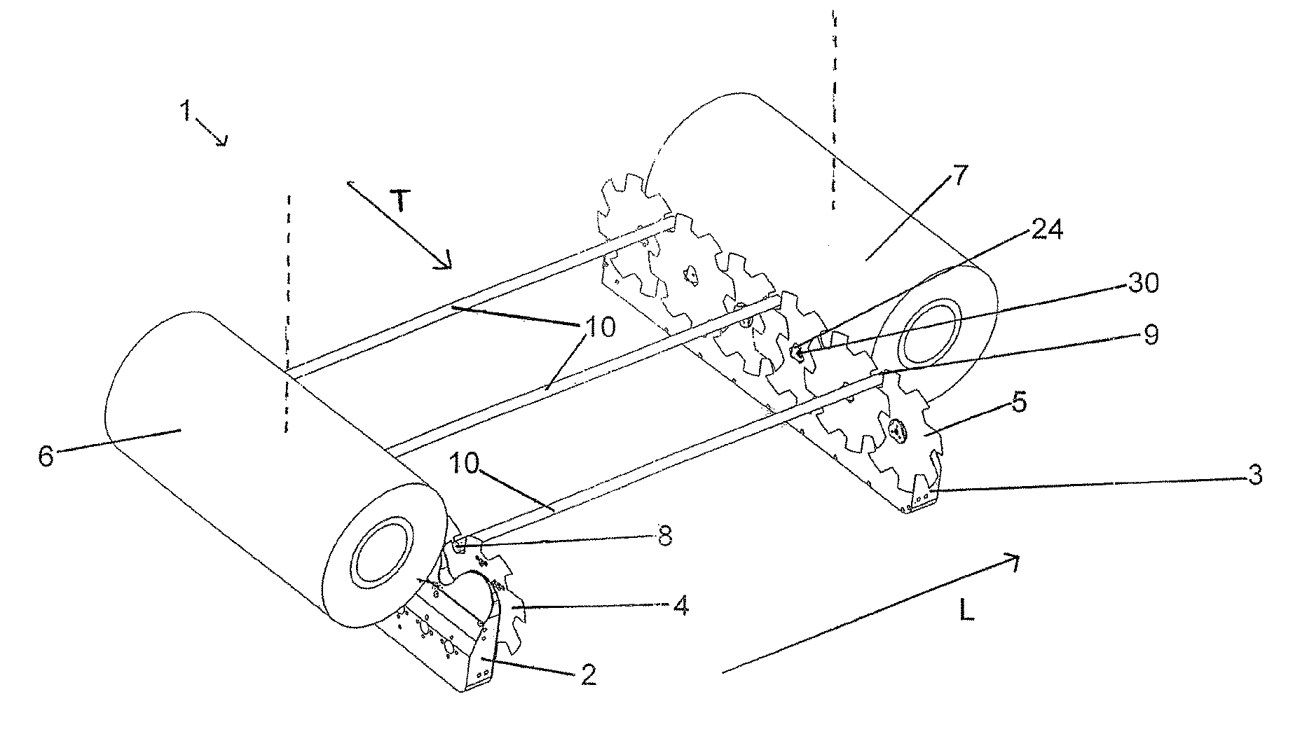
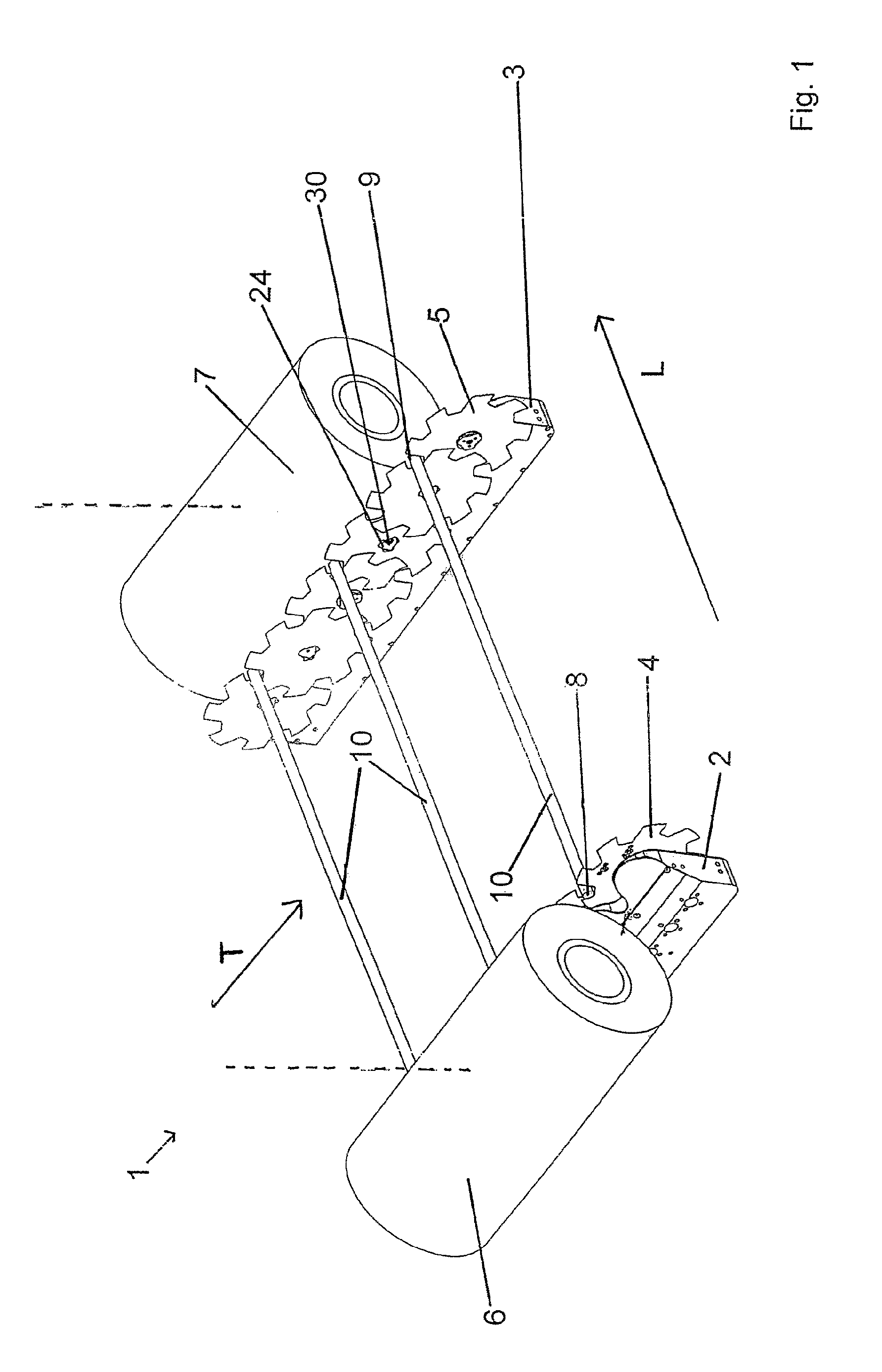
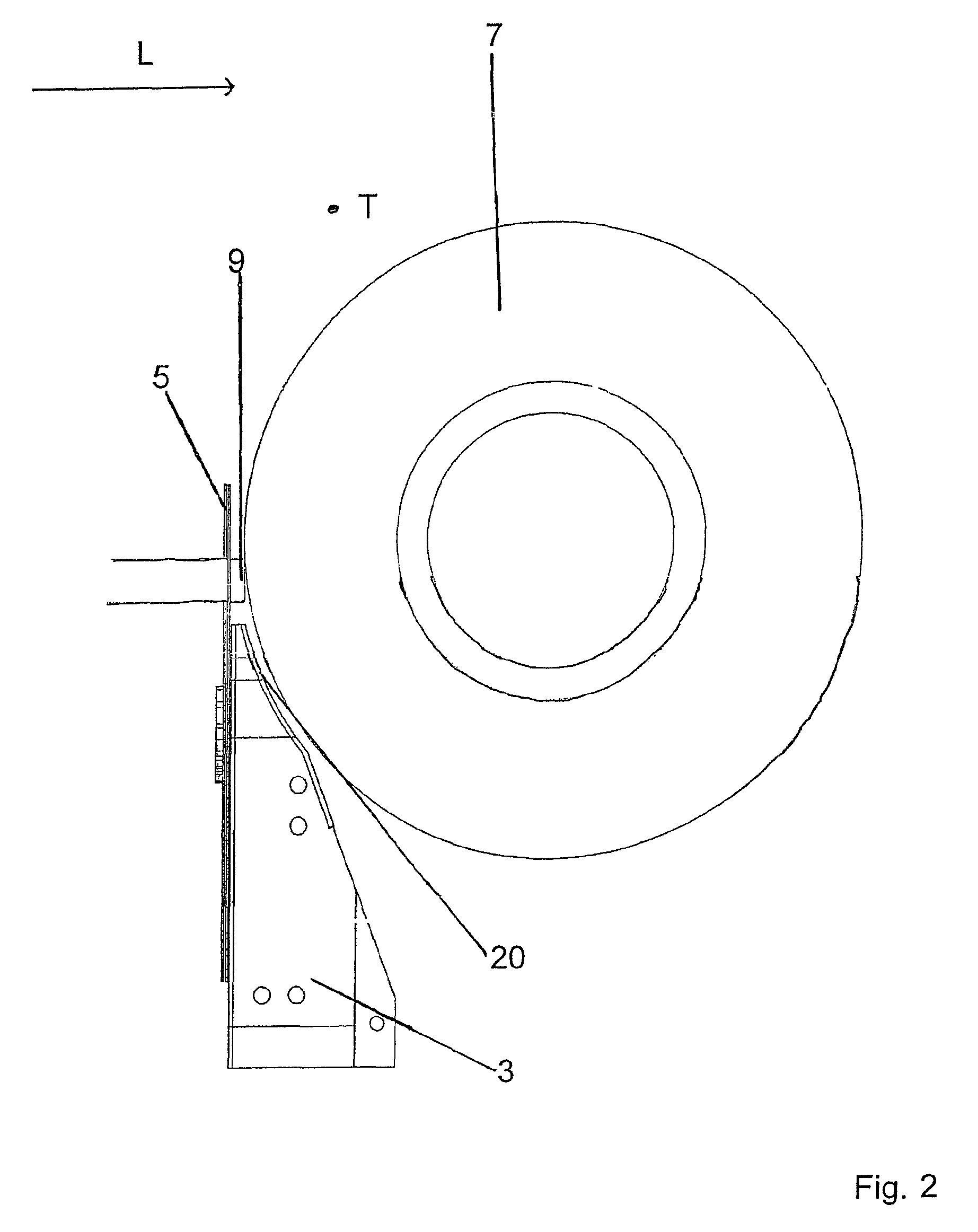
[0023]The brush-type deburring machine 1 illustrated diagrammatically in FIG. 1 has a first and a second frame arm 2, 3 which are orientated parallel to each other and which are orientated along a conveying direction T. A first row and a second row of conveying discs arranged offset one in the other are provided on the inner side of each of the two frame arms 2, 3. Each of the conveying discs of the two rows 4, 5 is arranged on the respective frame arm 2, 3 in a rotatable manner. On the outside a first brush roller 6 is arranged along the first frame arm 2 in a rotatable manner and a second brush roller 7 along the second frame arm 3, orientated in each case in the conveying direction T. The conveying discs are driven jointly and make it possible to advance sawn-off elongate profile sections 10 in the conveying direction T. In this case the elongate profile sections 10 are orientated at a right angle to the conveying direction T in the longitudinal direction L in each case. The elon...
PUM
| Property | Measurement | Unit |
|---|---|---|
| Length | aaaaa | aaaaa |
| Thickness | aaaaa | aaaaa |
| Size | aaaaa | aaaaa |
Abstract
Description
Claims
Application Information
 - R&D
- Intellectual Property
- Life Sciences
- Materials
- Tech Scout
- Unparalleled Data Quality
- Higher Quality Content
- 60% Fewer Hallucinations
Browse by: Latest US Patents, China's latest patents, Technical Efficacy Thesaurus, Application Domain, Technology Topic, Popular Technical Reports.
© 2025 PatSnap. All rights reserved.Legal|Privacy policy|Modern Slavery Act Transparency Statement|Sitemap|About US| Contact US: help@patsnap.com


