Pressure-gradient microphone capsule

Inactive Publication Date: 2005-04-26
AKG ACOUSTICS
View PDF3 Cites 40 Cited by
  • Summary
  • Abstract
  • Description
  • Claims
  • Application Information

AI Technical Summary

Benefits of technology

[0011]Therefore, it is the primary object of the present invention to provide a microphone capsule which operates according to the electrostatic principle and is constructed as an electroacoustic transducer according to the pressure-gradient pri

Problems solved by technology

However, microphone capsules according to the prior art are not capable of meeting this requirements and it is very difficult, expensive and technically cumbersome to mount the microphones in a flat surface. FIG. 2 of the drawing shows the usual mounting situation according to the prior art for a microphone capsule operating in accordance with the electrostatic principle.
However, this solution has the disadvantage that it has a great structural height or depth because the axis of symmetry of the capsule extends parallel

Method used


Image

  • Pressure-gradient microphone capsule
  • Pressure-gradient microphone capsule
  • Pressure-gradient microphone capsule

Examples


Embodiment Construction

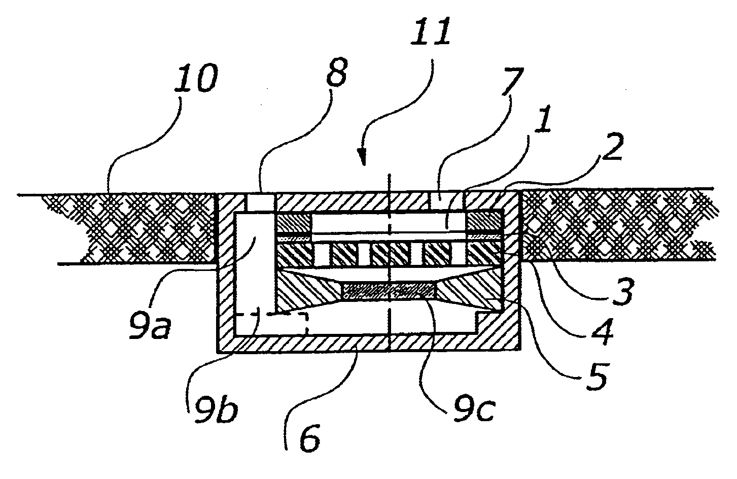
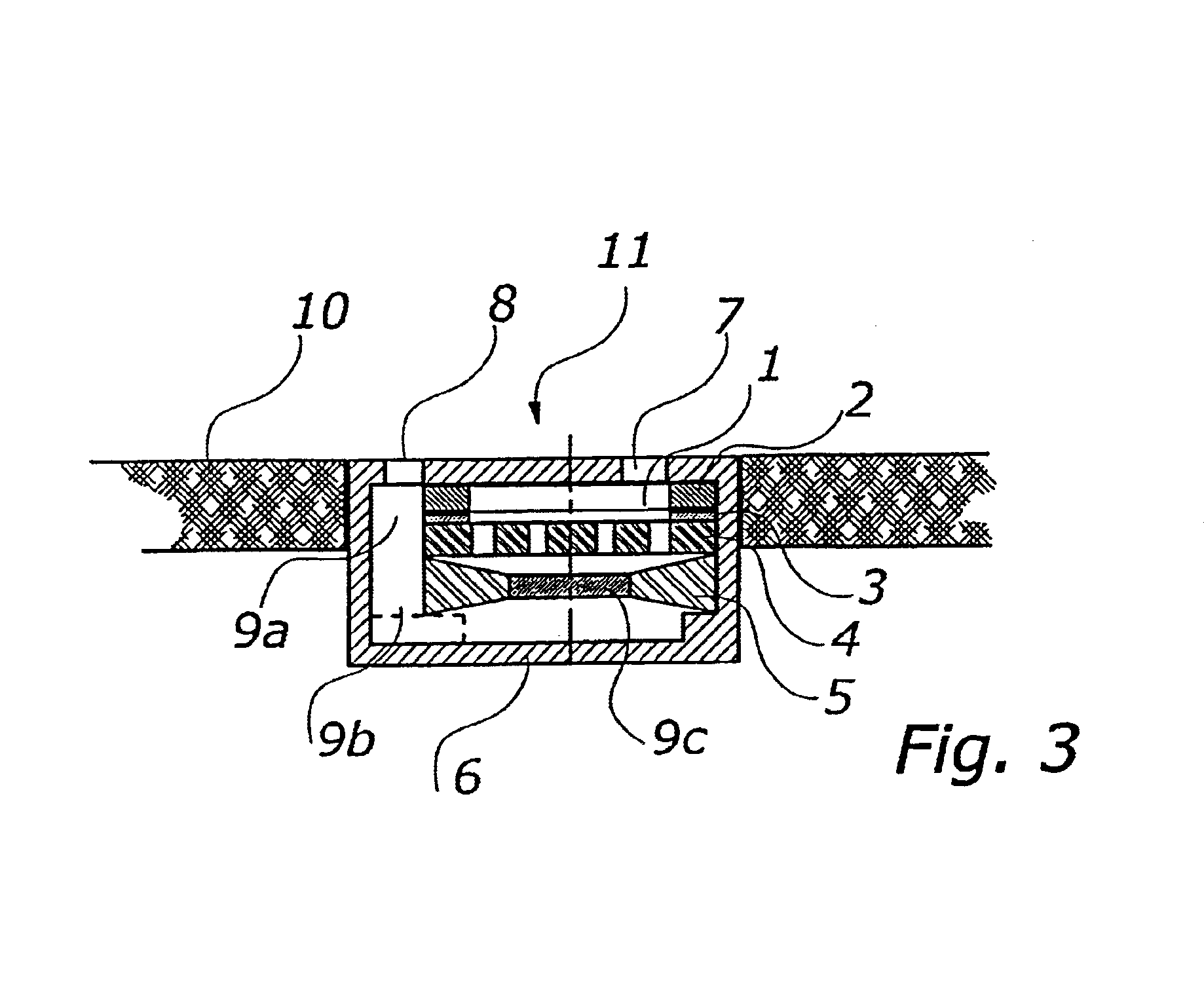
[0020]As illustrated in FIG. 3, a pressure-gradient capsule according to the present invention is essentially constructed as follows: a diaphragm 1 is tightly mounted and glued onto a diaphragm ring 2. The diaphragm 1 is mounted by means of a spacer ring 3 so as to be distanced from an electrode 4 by about 10 to 60 μm. The diaphragm 1 and the electrode 4 together form a capacitor. The electrode 4 is provided with bores. On the side of the electrode facing away from the diaphragm 1, a so called acoustic friction 5 is provided. The acoustic friction 5 usually is a plastic ring whose opening is covered by a porous material, such as metal screen fabric, sinter material, plastic fabric or natural fiber. The purpose of the acoustic friction 5 is to acoustically adjust the microphone capsule. In principle, this configuration is known in the art.

[0021]In accordance with the present invention, the capsule is mounted in a capsule housing 6. The capsule housing 6 is closed on its upper side, i...


PUM


Abstract

An electrostatic pressure-gradient microphone capsule to be mounted essentially flush in or behind especially flat mounting surfaces includes a capsule housing with two sound inlet openings which may be divided, a diaphragm tightly mounted on a diaphragm ring, an electrode and possibly an acoustic friction. The two sound entry openings are arranged on one side of the capsule housing, i.e., the front side, and one sound entry opening is connected acoustically conductively with the front side of the diaphragm and the other sound entry opening is connected acoustically conductively with the rear side of the diaphragm, and the diaphragm is arranged essentially parallel to the front side.

Description

BACKGROUND OF THE INVENTION[0001]1. Field of the Invention[0002]The present invention relates to an electrostatic pressure-gradient microphone capsule to be mounted essentially flush in or behind especially flat mounting surfaces. The microphone capsule includes a capsule housing with two sound inlet openings which may be divided, a diaphragm tightly mounted on a diaphragm ring, an electrode and possibly an acoustic friction.[0003]2. Description of the Related Art[0004]Independently of their physical manner of operation, electrostatic transducers for microphones have a diaphragm which is subjected to the field of sound and is excited to vibrations by the field of sound. Consequently, the invention is directed to an electrostatic microphone.[0005]The electrodes of the electrostatic transducer are an elastic, tightly mounted diaphragm and a rigid electrode which is usually just called electrode. Both electrodes form a capacitor whose electrical capacity changes as a result of pressure...

Claims


Application Information

Patent Timeline
IPC IPC(8): H04R19/00H04R1/38H04R19/04
CPCH04R1/38H04R19/04
Inventor PRIBYL, RICHARD
Owner AKG ACOUSTICS
Why Eureka
Try Eureka