
Device for suspending a rail of an overhead conveyor or a hoisting machine

a technology of hoisting machine and overhead conveyor, which is applied in the direction of runways, transportation and packaging, and ways, can solve the problems of long service life and achieve the effect of low structural height and long service li

Active Publication Date: 2008-02-21
KONECRANES GLOBAL
View PDF13 Cites 12 Cited by
  • Summary
  • Abstract
  • Description
  • Claims
  • Application Information

AI Technical Summary

Benefits of technology

[0015] The present invention provides a device for suspending a rail, such as a travel rail of an overhead conveyor or hoisting machine, which is secure, has a long service life, and has a low structural height.
[0016] According to the present invention, a device for suspending a rail, such as a travel rail of an overhead conveyor or a hoisting machine, from a traversing gear or supporting structure includes a tension element secured by one end to the rail. A bolt passes through the tension element and is received by a fixing device that is secured to the rail. The tension element is at least partly recessed in the fixing device in the direction of suspension. The tension element is fastened to the bolt by a ball-shaped joint, especially a pivoting bearing, which may achieve a secure construction as well as a long service life and a low structural height.
[0017] The bolt may be directly connected to the fixing device to minimize the structural height of the overall suspension and to increase the safety of the suspension. The use of a pivoting bearing may result in long service life. The design is simplified in that commercial, industrially manufactured pivoting bearings may be used, which are relatively low in wear and tear. Furthermore, considerable savings in the construction is achieved because no special parts are needed, as was formerly the case with the known suspension systems.
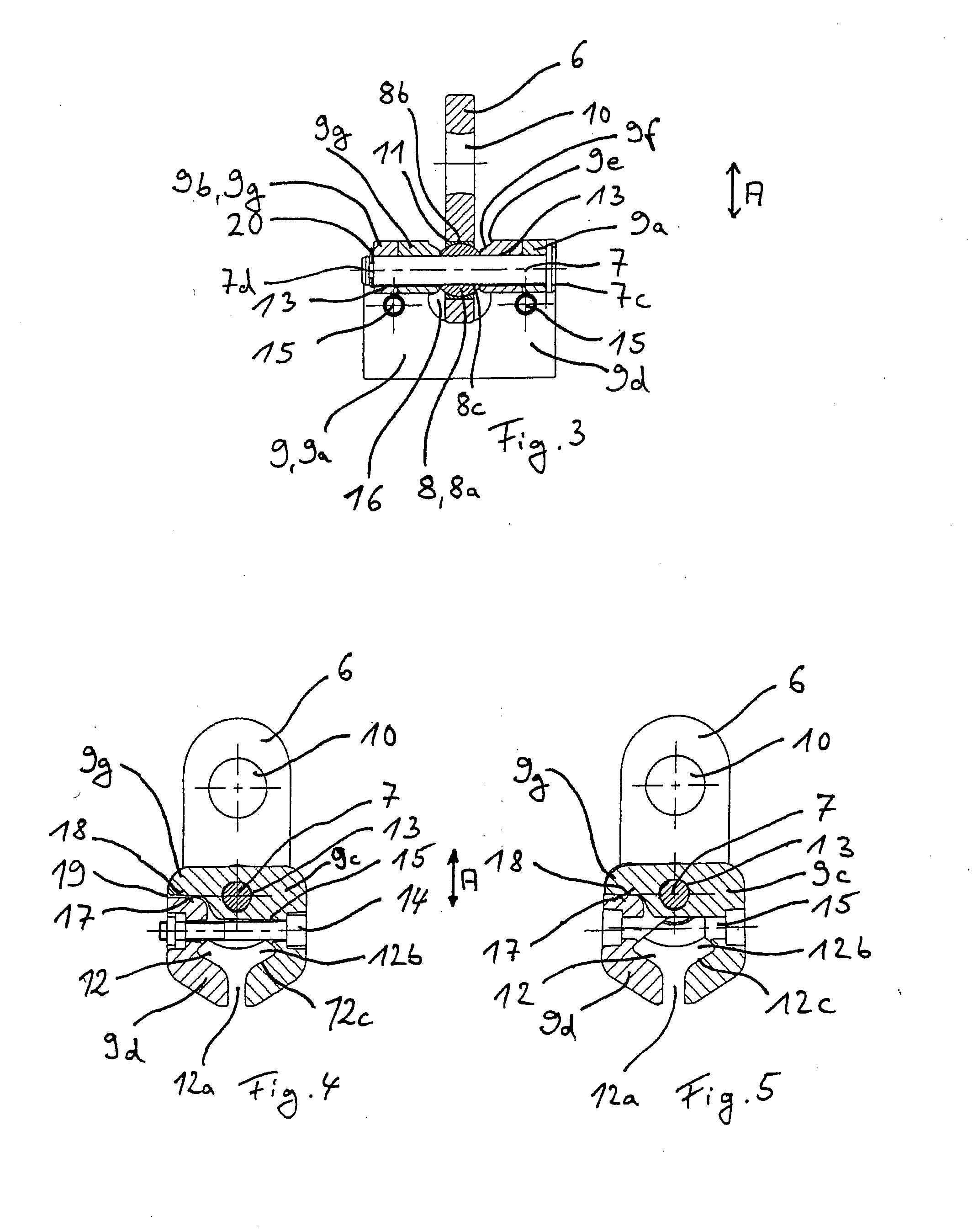
[0020] Further, to achieve a low structural height, the bolt may pass through the ball-shaped joint. The structural height is further minimized in that the bolt may be at least partly recessed into the fixing device in the direction of suspension. Optionally, the entire bolt may be completely recessed into the fixing device in the direction of suspension. This configuration facilitates a secure fastening of the bolt in the fixing device.
[0022] A secure connection of the bolt in the fixing device, and thus a direct flow of force, may be achieved in that the bolt may be held free of torsion in bores in the fixing device by its ends protruding at either side beyond the pivoting bearing. In this configuration, only the pivoting bearing is under stress due to the movements of the suspension system.

Problems solved by technology

The use of a pivoting bearing may result in long service life.

Method used


Image

  • Device for suspending a rail of an overhead conveyor or a hoisting machine
  • Device for suspending a rail of an overhead conveyor or a hoisting machine
  • Device for suspending a rail of an overhead conveyor or a hoisting machine

Examples


Embodiment Construction

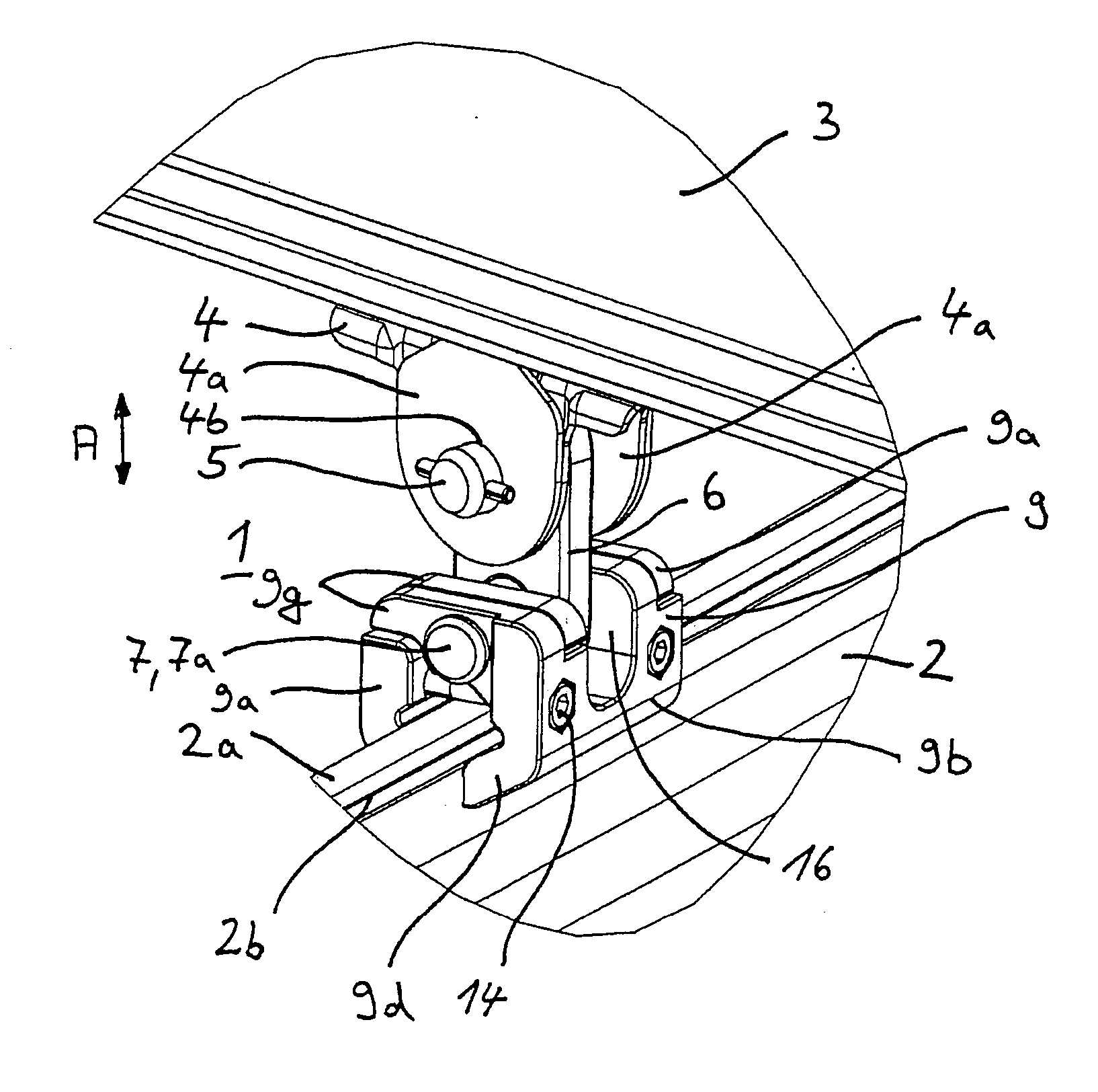
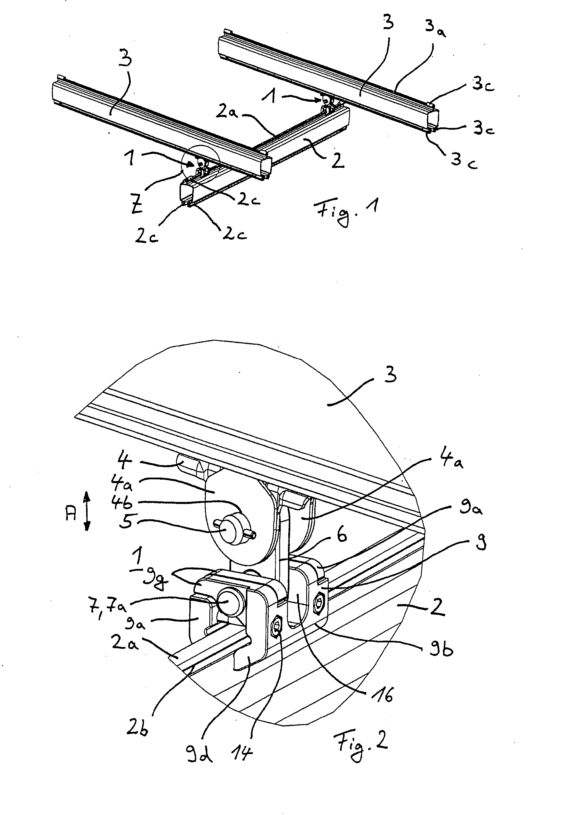
[0041] In FIGS. 1 and 2, a single-beam overhead crane 1 is shown with two suspensions, by which an essentially horizontal C-shaped rail 2, open at the bottom, is suspended from two essentially horizontal C-shaped travel rails 3, likewise open at the bottom, which are laid in parallel and at a distance from each other. The rail 2 travels essentially transverse to the travel rails 3 and can move along the travel rails 3. The rail 2 is suspended from a traversing gear 4 by the two suspensions 1 (see FIG. 2), which can travel in the travel rail 3 along its lengthwise direction by means of rollers (not shown). A hoisting machine (not shown), such as a chain or rope block, is hung from the rail 2 and can move with an additional traversing gear along the rail 2. Additional suspensions 1 (not shown) may be included along the travel rails 3, by which these may be suspended from supporting structures, other rails, or traversing gears.

[0042] Suspensions 1 have pivoting bearings and thus have ...


PUM


Abstract

A device for suspending a rail, such as a travel rail of an overhead conveyor or a hoisting machine, from a traversing gear or supporting structure includes a tension element secured by one end to the rail. A bolt passes through the tension element and is received by a fixing device that is secured to the rail. The tension element is at least partly recessed in the fixing device in the direction of suspension. In order to provide a secure device that has a long service life and a low structural height, the tension element is fastened to the bolt by a ball-shaped joint, such as a pivoting bearing.

Description

[0001] The invention pertains to a device for suspending a rail, and particularly to a device for suspending a travel rail of an overhead conveyor or a hoisting machine. BACKGROUND OF THE INVENTION [0002] From the prospectus (March 2000 edition) entitled “Crane Construction Kit KBK classic and KBK ergo” of the firm Demag Cranes & Components GmbH, Wetter, Germany, there is known a crane construction kit system with C-shaped and I-shaped rails which are open at the bottom, by which one can implement different kinds of constructions, such as monorail telphers and single and double-beam overhead cranes. In each case, the rails are suspended from support structures, other rails, or traversing gears which run into other rails. These suspension systems have a pendulum type design, which ensures that the rails align themselves and thus come into a state of equilibrium, i.e., no significant bending load occurs in the tension element. The pendulum suspension occurs through ball and socket bea...

Claims


Application Information

Patent Timeline
Patent Type & Authority Applications(United States)
IPC IPC(8): B66C7/08
CPCB66C7/04
Inventor BIRKIGT, REINHARDBUIKE, MICHAELENNERS, KLAUSFITZLER, STEFANGERSEMSKY, UDOGRASSMANN, INGOMULLER, SVENNERGER, KLAUSSTEINBERG, STEFANOSTHOLT, RUDIGER
Owner KONECRANES GLOBAL
Learn More