Advertising trays for security screening

a technology for advertising trays and security screening, applied in rigid containers, securing communication, program control, etc., can solve the problems of loose objects that can easily be lost or damaged, the trays for holding laptop computers are not part of a uniform system, and the laptop computers are delicate devices

Inactive Publication Date: 2005-08-11
SECURITYPOINT HLDG
View PDF39 Cites 50 Cited by
  • Summary
  • Abstract
  • Description
  • Claims
  • Application Information

AI Technical Summary

Benefits of technology

[0011] The present invention may eliminate the above-described disadvantages and provide for the above-described needs by teaching, for example, a system and device for use in securing a facility, and more particularly, by teaching a tray cart system and tray that may be used to contain various objects that are processed through a scanning device.

Problems solved by technology

These laptop computers are delicate devices which should not be dropped or jostled in an excessive amount as they can be damaged.
These items are typically loose objects that can easily be lost or damaged if not handled in a safe manner.
A disadvantage to the present system used in security areas is that the trays for holding laptop computers are not part of a uniform system and do not protect the items from possible damage.
Therefore, it is possible that multiple size trays that do not in any way correspond with one another may be used at a security area thus making storage of the trays when they are not in use cumbersome.
A disadvantage to a non-standardized tray system is that when the trays are to be stored they may take up passenger access areas, thereby causing further waiting time as the security personnel moves the unused trays so that a person may pass through a passenger access area.
Further it is common that there are inadequately-sized trays for holding large items such as laptop computers, thereby increasing the chance of the computers being damaged by being placed on a conveyer belt without being placed in a tray through an x-ray machine.
Also, the time taken to search for a possible adequately-sized tray creates inefficiency and extends the waiting time while a person is passing through a passenger access area.
Another disadvantage of the present system is that after the trays are used and the contents are empted the tray must then be brought to a separate area of the security area and there is no system for transporting, storing and organizing for easy access to these trays especially if there are large numbers of them, and since the trays may be of various sizes, they may be cumbersome to transport and take up an excessive amount of space.
A disadvantage to the prior system is that the trays which are being used typically are plain trays and do not utilize space provided on the trays to generate additional revenue such as revenue which can be derived from advert / sing on the trays.

Method used


Image

  • Advertising trays for security screening
  • Advertising trays for security screening
  • Advertising trays for security screening

Examples


first embodiment

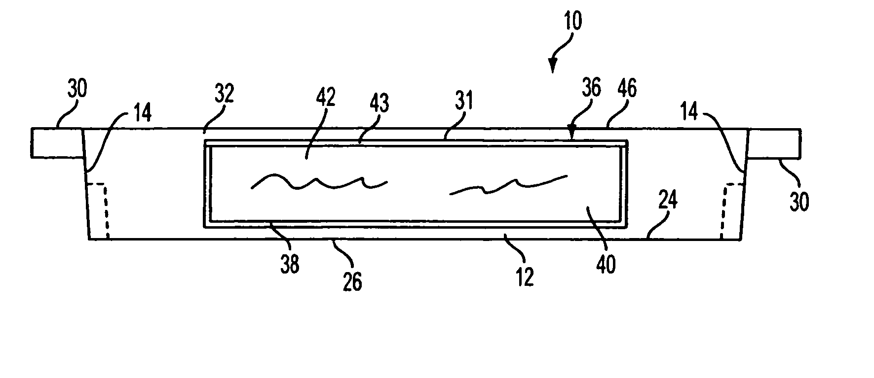
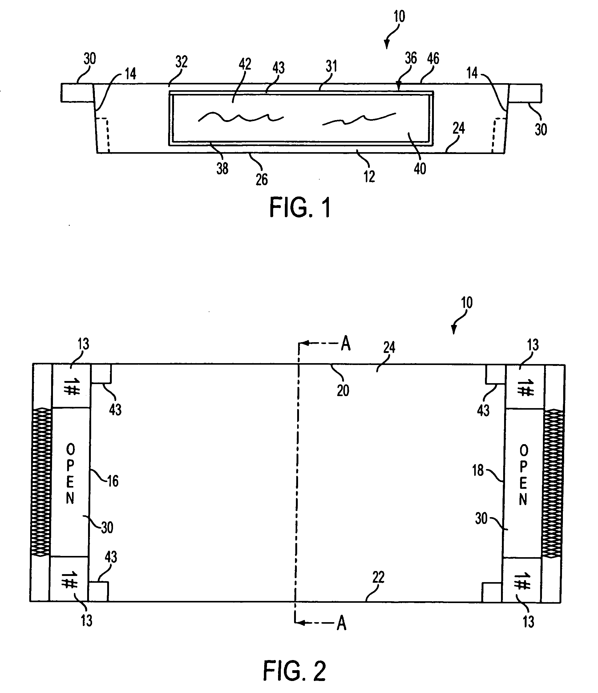
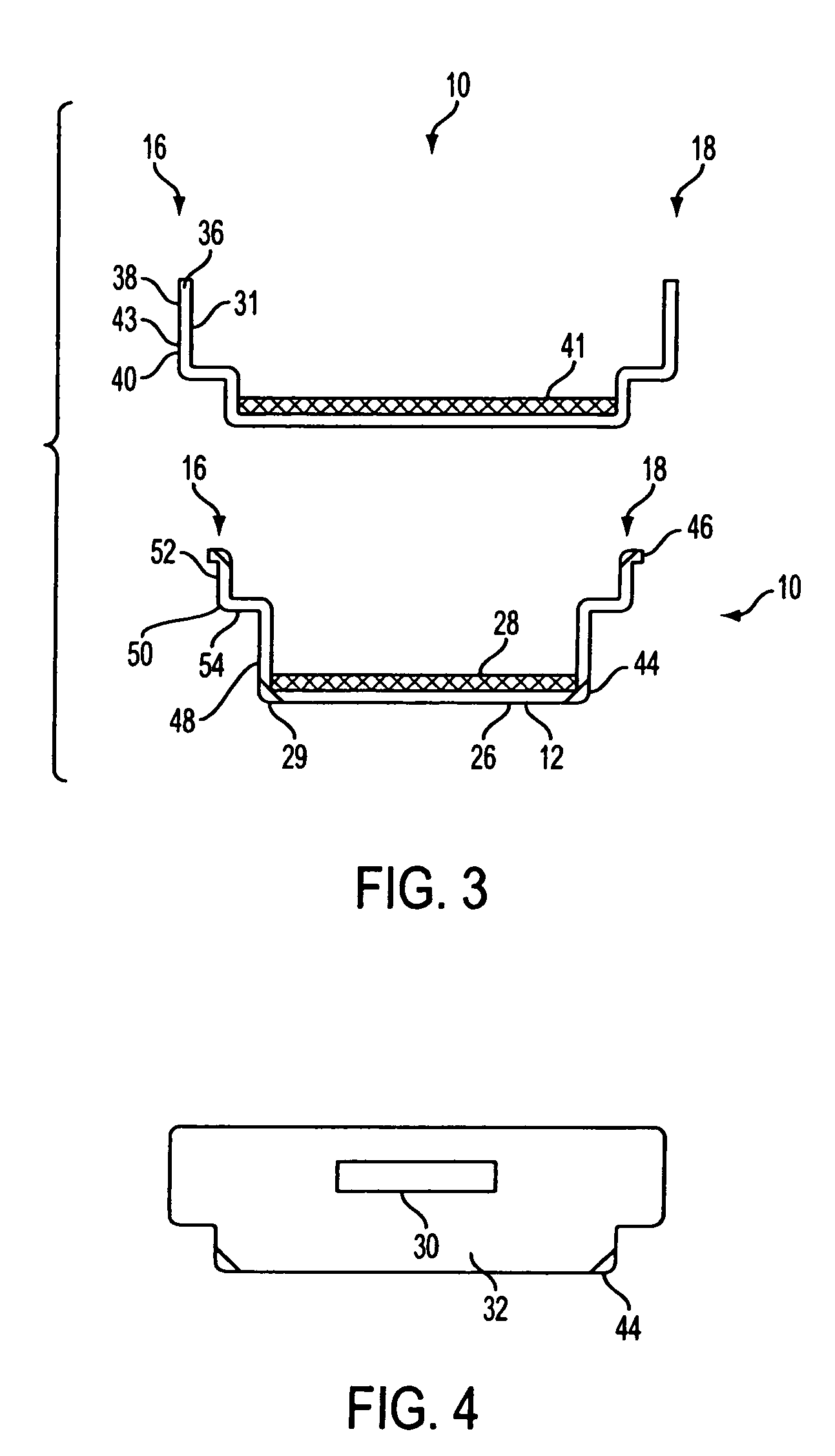
[0048] Referring to FIG. 1, the side elevation view of a computer tray first embodiment is shown. The tray 10 has a base 12 having upwardly extending walls 14 extending therefrom. In a preferred embodiment, base 12 can have a rectangular or square shape. Referring to FIG. 2, there is a first wall 16 and a second wall 18 positioned substantially parallel to the first wall. The first wall 16 and second wall 18 are connected to each other by a substantially perpendicular third wall 20 and a fourth wall 22 parallel to the third wall 20. Referring to FIG. 1, the walls 14 terminate at an upper lip 46.

[0049] Referring to FIG. 2, attached adjacent the first wall 16 and second wall 18 can be an extended portion to form a handle 30 so that the tray can be easily moved by the user. The tray can be made of plastic by injection molding or in the alternative by stamping out of PVC or a similar material. However, any method of making the tray can be used. The tray can be made of a clear or translu...

fifth embodiment

[0071]FIG. 11 is a top view diagram of the present invention. In this embodiment the overall width may be about 21.61 inches and the interior width measure from (referring to FIG. 3) one first section 48 to the opposite first section 48 may be about 15.81 inches. In FIG. 11, the overall vertical length may be about 13.81 inches.

[0072]FIG. 12 is a side view diagram of a fifth embodiment of the present invention. The vertical height of this embodiment may be about 5.0 inches and the height of (referring to FIG. 1) handle 30 may be about 0.63 inches.

[0073]FIG. 13 is a perspective view of the fifth embodiment of the present invention illustrating the placement of a tag number 13 and advertising windows 36.

[0074]FIG. 14 is an end view of the fifth embodiment of the present invention. It may be similar in appearance to a side view of the same embodiment.

sixth embodiment

[0075]FIG. 15 is a top view diagram of the present invention. In this embodiment the overall width may be about 13.00 inches and the interior width measure from (referring to FIG. 3) one first section 48 to the opposite first section 48 may be about 8.81 inches. In FIG. 15, the overall vertical length may be about 12.00 inches.

[0076]FIG. 16 is a side view diagram of a sixth embodiment of the present invention. The vertical height of this embodiment may be about 5.0 inches and the height of (referring to FIG. 1) handle 30 may be about 0.63 inches.

[0077]FIG. 17 is a perspective view of the sixth embodiment of the present invention illustrating the placement of a tag number 13 and advertising windows 36.

[0078]FIG. 18 is an end view of the sixth embodiment of the present invention. It may be similar in appearance to a side view of the same embodiment.


PUM


Abstract

A system and device for use in a security area, and more particularly, a rack system and holding device for placing various objects that are processed through a security area are taught.

Description

CROSS REFERENCE TO RELATED APPLICATIONS [0001] The present application is related to and claims the benefit under 35 U.S.C. § 119(e) of U.S. Provisional Patent Application Ser. No. 60 / 393,637 filed Jul. 3, 2002, which is expressly incorporated fully herein by reference.FIELD OF THE INVENTION [0002] The present invention relates generally to a system and device for use in a security area, and more particularly, to a rack system and holding device for placing various objects which are processed through a security area. BACKGROUND OF THE INVENTION [0003] Security areas are typically encountered in places such as an airport security terminals, courthouse entrances and various other places where a person and their luggage or personal items may need to be searched prior to entering or leaving a particular room or area of a building. These security areas typically involve the steps of a person moving through a metal detector area and removing various items from their clothing, pockets or l...

Claims


Application Information

Patent Timeline
Patent Type & Authority Applications(United States)
IPC IPC(8): A47G19/03A47G23/06B65D1/34B65D21/02B65D25/20B65D81/38B65D85/00G08B13/00G09F23/00G21K1/12H05G1/60
CPCB65D1/34B65D25/205G09F23/00B65G49/00B65G47/74G01V5/0016B62B3/006B62B3/10B65D85/00A47B81/00
Inventor AMBREFE, JOSEPH T. JR.
Owner SECURITYPOINT HLDG
Why Eureka
Try Eureka